Electronic control for a hydraulically driven auxiliary power source
a technology of electric control and hydraulic system, applied in the direction of electric generator control, positive displacement liquid engine, fluid coupling, etc., can solve the problems of engine electrical power, engine speed variations wreak havoc, and difficulty in maintaining precise frequency output for controlling
- Summary
- Abstract
- Description
- Claims
- Application Information
AI Technical Summary
Benefits of technology
Problems solved by technology
Method used
Image
Examples
third embodiment
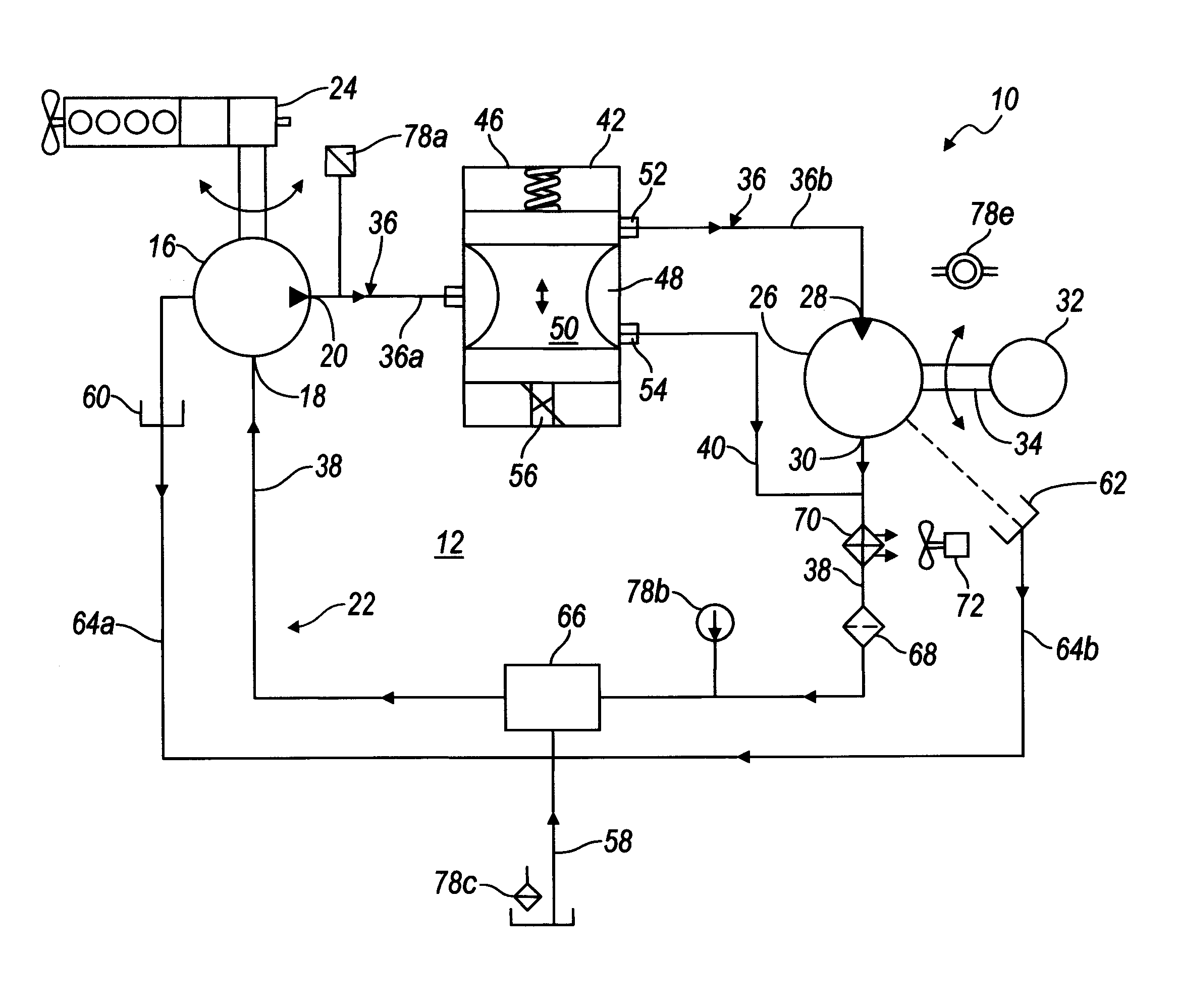
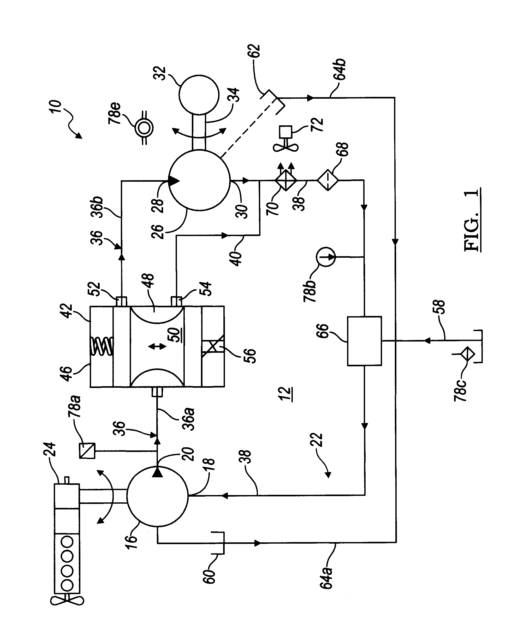
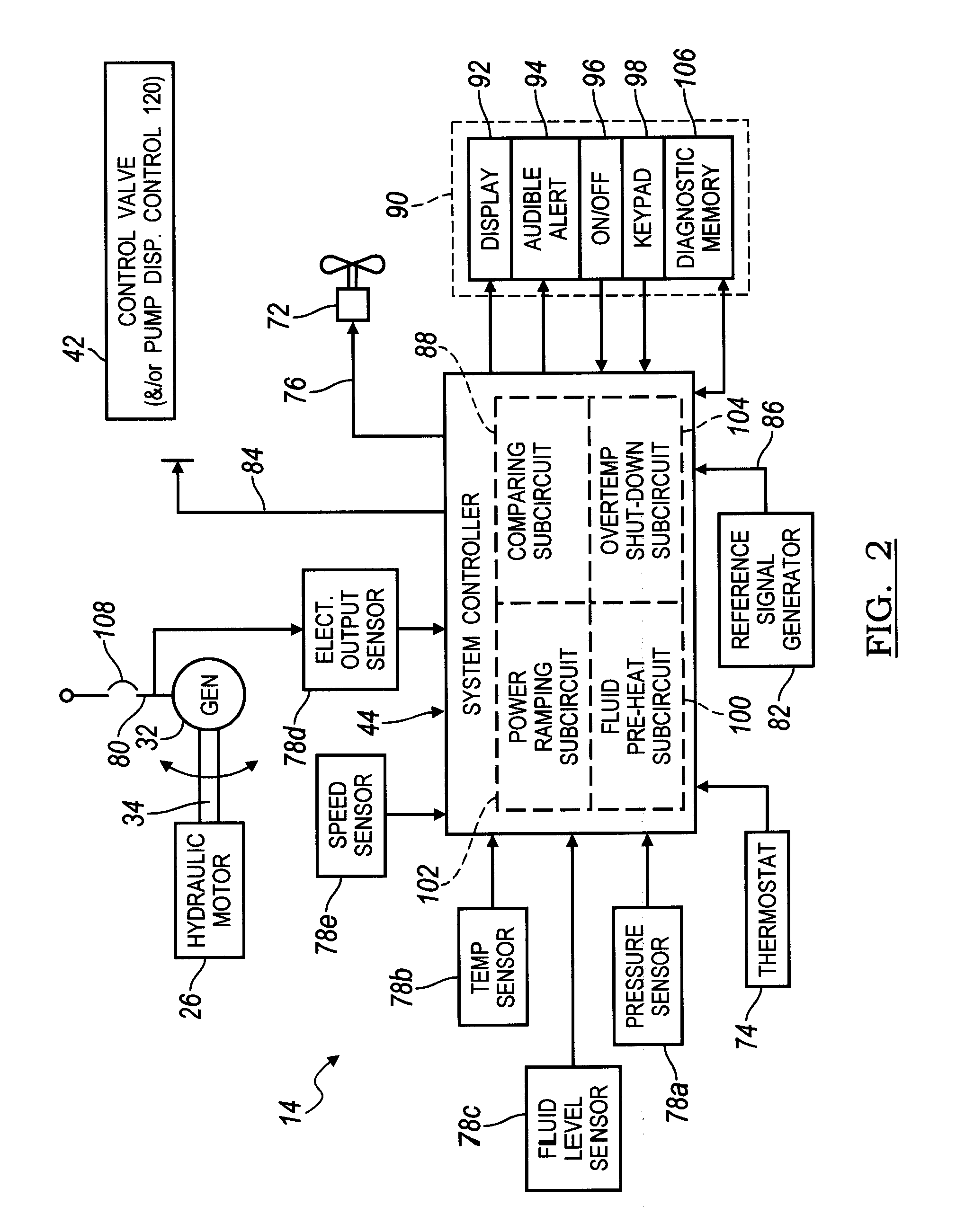
[0078]the present invention is illustrated in FIG. 5. A hydraulically driven generator system 110 is similar to system 10 described with reference to FIG. 1, however rather than using a control valve assembly 42 to regulate the amount of the output of pump 16 that passes through motor 26, a variable displacement pump 112 is utilized which has an external input which enables the control system to vary the pump displacement to achieve the desired flow rate needed for motor 36. Hydraulic control circuit 114 of the FIG. 5 embodiment is otherwise generally similar to control circuit 12 utilized in the FIG. 1 embodiment and like components function in a similar manner as described previously.
[0079]In operation the output from pump 112 provides hydraulic fluid to motor 26. As previously described, control valve 42 is utilized in the FIG. 1 embodiment is no longer required provided the pump minimum displacement is sufficiently low. If the minimum pump displacement is substantial, i.e., over...
seventh embodiment
[0090]Referring now to FIG. 12, with continual reference to FIG. 1, the present invention is illustrated. A hydraulically driven generator system 10 shown in FIG. 12 is the same as system 10 described with reference to FIG. 1 with the exception that one or more additional control valve assemblies 131, 132 are employed. For instance, system 10 may include a control valve assembly 132 disposed serially and / or parallel with respect to supply conduit 36 such that it is interposed between outlet 20 of pump 16 and control valve assembly 42. Control valve assembly 132 may be employed to warm and / or isolate and protect the rest of system 10 from conditions existing at pump 16 such as cold hydraulic fluid. Control valve assembly 132 may be slowly opened to allow fluid to propagate to the rest of system 10 as conditions improve such as the hydraulic fluid warming to an appropriate temperature.
PUM
 Abstract
Description
Claims
Application Information
 - R&D
- Intellectual Property
- Life Sciences
- Materials
- Tech Scout
- Unparalleled Data Quality
- Higher Quality Content
- 60% Fewer Hallucinations
Browse by: Latest US Patents, China's latest patents, Technical Efficacy Thesaurus, Application Domain, Technology Topic, Popular Technical Reports.
© 2025 PatSnap. All rights reserved.Legal|Privacy policy|Modern Slavery Act Transparency Statement|Sitemap|About US| Contact US: help@patsnap.com


