
Novel coal mine bracket

A coal mine, a new type of technology, applied in the field of new coal mine brackets, can solve the problems of safety accidents, inability to use, loss, etc., and achieve the effects of avoiding safety accidents, moving conveniently, and reducing wear and tear

Inactive Publication Date: 2018-05-22
SICHUAN GUANTENG TECH CO LTD
View PDF0 Cites 4 Cited by
  • Summary
  • Abstract
  • Description
  • Claims
  • Application Information

AI Technical Summary

Problems solved by technology

[0003] Based on the above technical problems, the present invention provides a new type of support for coal mines, thereby solving the problem that the brake blocks or tools hung on the support in existing coal mines are dropped due to coal explosion, damaged or lost, resulting in unusability, and even safety accidents. technical issues

Method used


Image

  • Novel coal mine bracket
  • Novel coal mine bracket
  • Novel coal mine bracket

Examples


Embodiment 1

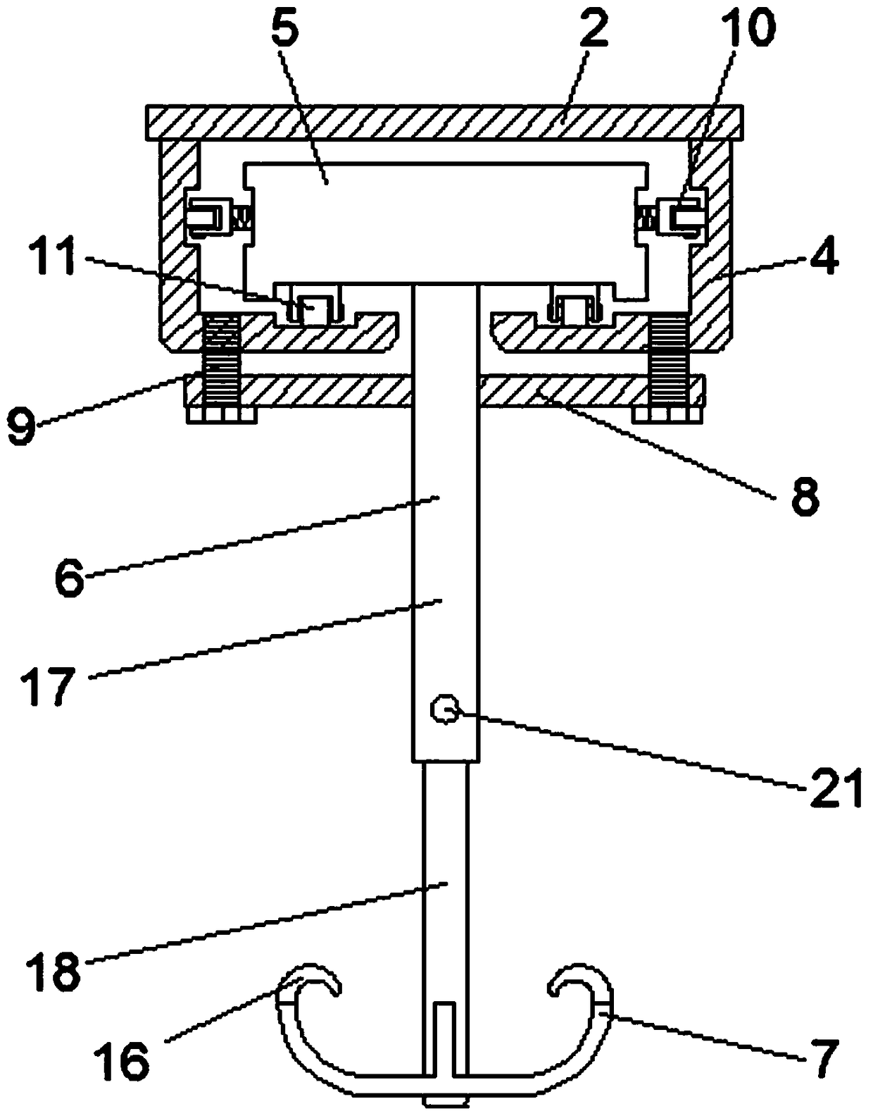
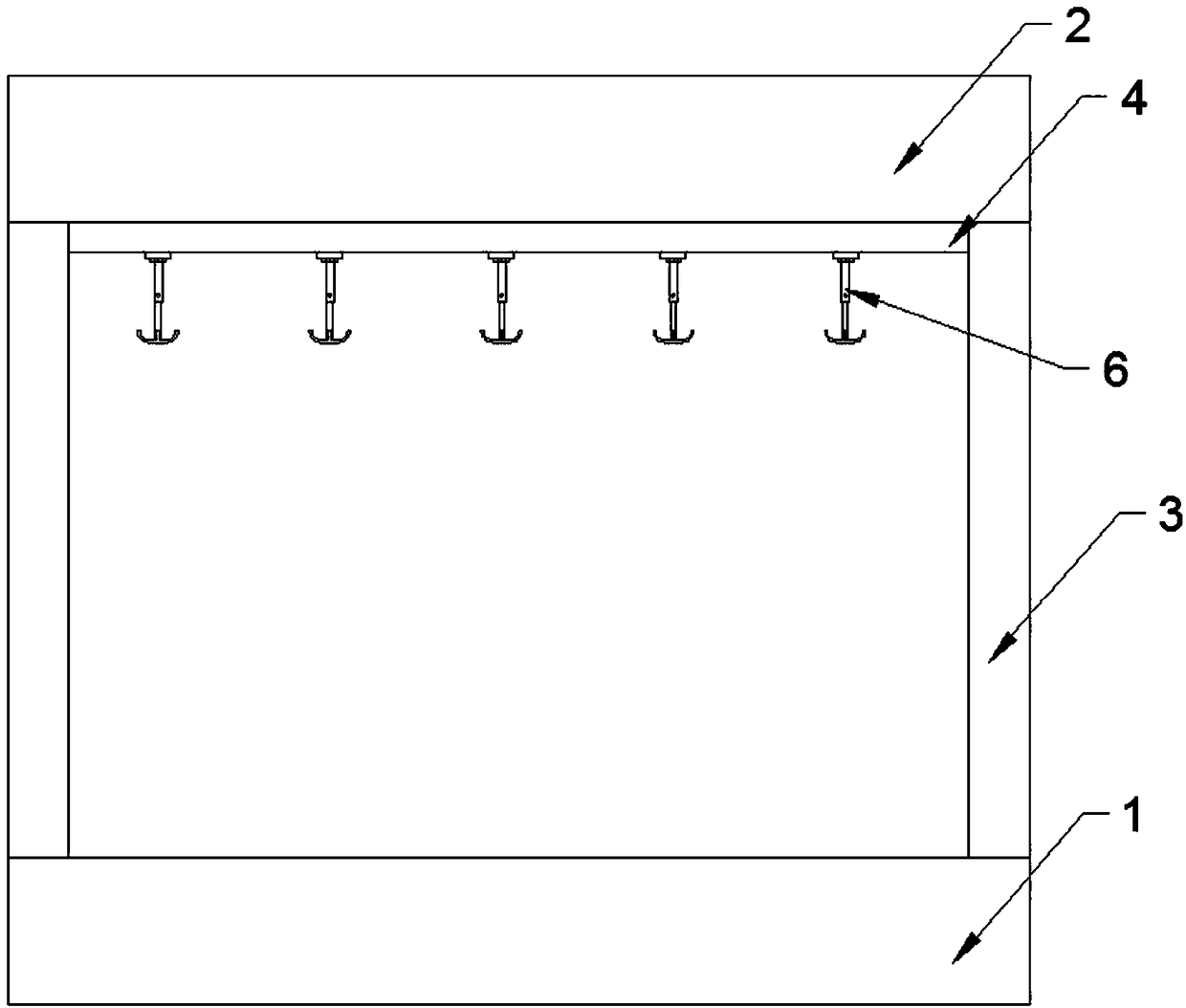
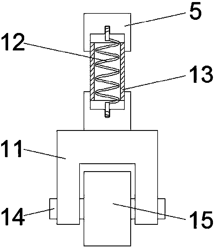
[0027] A new type of support for coal mines, including a base 1 and a crossbar 2 arranged on the base 1, a connecting rod 3 is vertically arranged between the base 1 and the crossbar 2, and a rail 4 is horizontally arranged at the bottom of the crossbar 2, and the rail 4 is provided with a plurality of suspension devices that can slide along the track 4. The suspension device includes a body 5, a hanging rod 6 arranged at the bottom of the body 5, and a hook 7 arranged at the bottom of the hanging rod 6; both sides of the hanging rod 6 are located at the bottom of the track 4 A connecting plate 8 is arranged horizontally, and a through hole is arranged on the connecting plate 8, and a connecting hole is arranged on the corresponding through hole on the track 4, and the through hole and the connecting hole are connected by a bolt 9;

[0028] The body 5 is stuck in the track 4, and both sides below the body 5 are provided with longitudinal wheels 10, and both sides of the body 5 ...

Embodiment 2

[0030] This embodiment is further optimized based on Embodiment 1. The hanging rod 6 includes a hollow outer rod 17 arranged at the bottom of the body 5, a solid inner rod 18 arranged below the hollow outer rod 17, and the interior of the hollow outer rod 17 passes through a central axis 19. A clamping rod 20 is provided, and a button 21 is disposed above one end of the clamping rod 20 , and a second return spring 22 is disposed below one end of the clamping rod 20 , so that the length of the hanging rod 6 can be adjusted as required.

Embodiment 3

[0032] This embodiment is further optimized based on Embodiment 2. The solid inner rod 18 is evenly provided with grooves 23 on the side of the clamp rod 20. After 20 is fixed, due to the excessive external force, the clamping rod 20 and the solid inner rod 18 will slide relative to each other.


PUM


Abstract

The invention relates to the technical field of coal mine mechanical devices, and discloses a novel coal mine bracket which comprises a base and a transverse rod arranged on the base. A rail is arranged at the bottom of the transverse rod and internally provided with a plurality of hanging devices. Each hanging device comprises a body, a hanging rod and a hook, wherein connecting plates for beingconnected with the rail are horizontally arranged on the two sides of the hanging rod and at the lower portion of the rail, transverse wheels are arranged on the two sides of the body, first reset springs are arranged between the transverse wheels and the body, and an anti-disengagement hook is welded to the end of the hook. The hooks can move along the rail, and the distances between the hooks can be conveniently adjusted; the connecting plates arranged on the hanging rods can fix the hooks after adjustment, and hooks are prevented from sliding relatively; the first reset springs can shake onthe bracket, the hooks are buffered to a certain extent, the shaking amplitude of the hooks is reduced, and brake blocks or tools on the hooks are prevented from falling off through the cooperation of the first reset springs and the anti-disengagement hooks.

Description

technical field [0001] The invention relates to the technical field of coal mine machinery, in particular to a novel support for coal mines. Background technique [0002] At present, when coal mines are working underground, brackets are often placed at the junction of each roadway, and brackets such as for fixing mine cars are hung on the brackets. Figure 5 The brake block shown is convenient to fix the mine car when there are too many mine cars at the junction of the roadway; some common tools will also be hung on the bracket. The brake pads or tools on the bracket are shaken off, resulting in damage to the brake pads or tools, or even loss; making people unable to use them when they are in use, because after the brake pads are lost, workers will use other irregular objects in violation of regulations because they are anxious to complete the task. Securing minecarts or even not securing minecarts leads to safety accidents. Contents of the invention [0003] Based on the...

Claims


Application Information

Patent Timeline
Patent Type & Authority Applications(China)
IPC IPC(8): A47B81/00A47B97/00E21F17/00B61K7/16F16F15/04
CPCA47B81/00A47B97/00B61K7/16E21F17/00F16F15/04
Inventor 青学刚
Owner SICHUAN GUANTENG TECH CO LTD
Learn More