Automobile spare part machining mold

A technology for processing molds and spare parts, which is applied in the field of processing molds for auto parts. It can solve the problems of inconvenient cleaning of debris in stamping molds, and achieve the effects of convenient manual processing and assembly, low production costs, and improved manufacturing accuracy.

Inactive Publication Date: 2018-05-22
广州大汗科技有限公司
View PDF11 Cites 2 Cited by
  • Summary
  • Abstract
  • Description
  • Claims
  • Application Information

AI Technical Summary

Problems solved by technology

[0005] The purpose of the present invention is to solve the defect of inconvenient cleaning of debris in stamping dies in the prior art, and to provide a processing die for auto parts to solve the above problems

Method used


Image

  • Automobile spare part machining mold
  • Automobile spare part machining mold
  • Automobile spare part machining mold

Examples


Embodiment Construction

[0019] In order to have a further understanding and understanding of the structural features of the present invention and the achieved effects, the preferred embodiments and accompanying drawings are used for a detailed description, as follows:

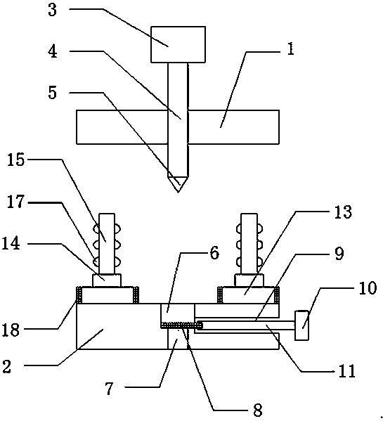
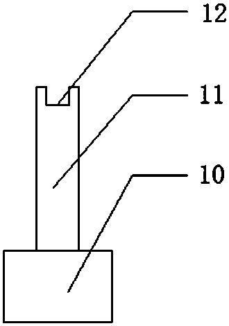
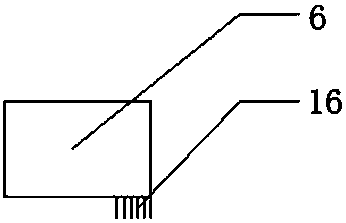
[0020] Refer to attached Figure 1-3 As shown, a mold for processing auto parts includes a lower mold 2 and an upper mold 1 opposite to the lower mold 2. A stamping cylinder 3 is arranged above the upper mold 1, and an output shaft 4 at the end of the stamping cylinder 3 runs through the upper mold 1. Set in the center, a stamping head 5 is provided under the output shaft 4, a stamping groove 6 is provided at the center of the lower die 2, the stamping groove 6 is located directly below the stamping head 5, and a discharge hole is provided below the stamping groove 6 7. A baffle 8 is provided between the stamping groove 6 and the discharge hole 7, a rectangular channel 9 is arranged axially on the right side of the lower die 2, and a ...


PUM


Abstract

The invention discloses an automobile spare part machining mold which comprises a lower mold and an upper mold opposite to the lower mold. A punching air cylinder is arranged above the upper mold. Anoutput shaft of the tail end of the punching air cylinder is arranged in a manner of penetrating the center of the upper mold. A punching head is arranged below the output shaft. A punching groove isformed in the center of the lower mold and located under the punching head. A discharging hole is formed below the punching groove. A baffle is arranged between the punching groove and the discharginghole. A rectangular channel is arranged in the axial direction of the right side of the lower mold. A telescopic air cylinder is arranged on the right side of the lower mold. A telescopic shaft at the tail end of the telescopic air cylinder extends into the channel. A clamp groove with the width matched with that of the baffle is formed in the tail end of the telescopic shaft. The baffle can slide left and right relative to the punching groove. Compared with the prior art, the automobile spare part machining mold of the scheme cannot generate any impact damage, and the problem that chippingsare inconvenient to remove in an existing punching mold is solved; and meanwhile, structure manufacturing is simple, manual machining and assembling are convenient, the production cost is low, and useby operation workers is convenient.

Description

technical field [0001] The invention relates to the technical field of auto parts processing, in particular to a mold for processing auto parts. Background technique [0002] Mold refers to various molds and tools used in industrial production for injection molding, blow molding, extrusion, die-casting or forging forming, smelting, stamping and other methods to obtain the required products. In short, a mold is a tool used to make shaped objects. This tool is composed of various parts, and different molds are composed of different parts. It mainly realizes the processing of the shape of the article through the change of the physical state of the formed material. [0003] With the rapid development of the national economy, automobiles have become the main means of transportation for people, followed by the vigorous development of the automobile industry. Due to the limitations of the use environment, auto parts require high manufacturing precision and assembly precision. Th...

Claims


Application Information

Patent Timeline
Patent Type & Authority Applications(China)
IPC IPC(8): B21D37/10B21D43/00B08B1/02
Inventor 刘建军韩静
Owner 广州大汗科技有限公司
Why Eureka
Try Eureka