
Aeration and oxygen increase device

An oxygen-enhancing device and aeration technology, which is applied in the fields of fishery aquaculture equipment and oxygen-enhancing aeration devices, can solve the problems of small contact area, inability to better solve the phenomenon of water stratification in pools, and inability to realize large-scale agitation in water areas. , to achieve uniform aeration and increase the effect of oxygen

Active Publication Date: 2018-05-25
大连天裕泵业有限公司
View PDF3 Cites 0 Cited by
  • Summary
  • Abstract
  • Description
  • Claims
  • Application Information

AI Technical Summary

Problems solved by technology

[0003] However, the existing various forms of impellers pass through the flow channels formed between each blade of the impeller, and the gas and water mixture flows along the flow channels between the blades and then is thrown out to the surrounding waters, thereby increasing the oxygen content of the water body. or use the impeller disc as a whole to rotate through the air channel in the impeller disc to discharge air, and then realize aeration; this method only plays the role of aeration, and the contact area between the impeller disc and the water body is small when it rotates, so it cannot Realize large-scale agitation in the water area; cannot better solve the pool water stratification phenomenon; in the existing design, there is no air channel through the impeller itself, so that the gas in several air channels can aerate the water area, aerate evenly, and improve aeration High efficiency, fully realize the increase in breeding income; and increase the contact area with the water body through several air channels, realize a large-scale agitation in the water area, and solve the phenomenon of pool water stratification

Method used


Image

  • Aeration and oxygen increase device
  • Aeration and oxygen increase device
  • Aeration and oxygen increase device

Examples


Embodiment Construction

[0031] The present invention will be described in detail below in conjunction with the accompanying drawings.

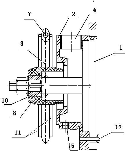
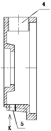
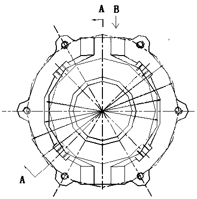
[0032] The oxygen-increasing aeration device shown in the figure includes a motor end 1, an air guide shell 2, and an aeration wheel 3. 1 Bolt holes are provided at both ends, and the extension of the air guide shell 2 is provided with holes matching the bolt holes of the motor end. The motor end 1 is fixedly connected with the air guide shell 2 through bolts 12; The side ends of the gas shell 2 are respectively provided with a first through hole 4 and a second through hole 5. The aeration wheel 3 is formed by a number of support wheels 6 spirally arranged, and each support wheel 6 is provided with an air channel 7 through the center. There is a cavity in the center of the aeration wheel 3, and a part of the central axis of the motor end is set in the cavity;

[0033] The diameter of the first through hole 4 is larger than the diameter of the second through hole 5; ...


PUM


Abstract

Provided is an aeration and oxygen increase device. The device includes a motor end, an air-guiding shell and an aeration wheel, a central shaft of the motor end is arranged in a penetrating mode at the center positions of the air-conducting shell and the aeration wheel sequentially, and bolt holes are respectively formed in both ends of the motor end, holes matched with the bolt holes in the motor end are formed in the extension position of air-guiding shell, and the motor end is fixedly connected with the air-guiding shell through bolts; a first through-hole and a second through-hole are respectively formed in side ends of the air-conducting shell at both sides of the central shaft of the motor end, and the aeration wheel is formed by a plurality of supporting wheels which are spirally arranged, air passages are formed in each of the supporting wheels in a center penetrating mode, a chamber is formed in the center of the aeration wheel, and a part of the central shaft of the motor end is disposed in the chamber. The device integrates oxygen increase, water activation and aeration, the amount of dissolved oxygen in water is effectively increased, the cycle of matter in the water is accelerated, suffocation is prevented, water quality conditions are improved, the problem of pool water stratification is solved, the yield of sea cucumber breeding is improved, stocking density isimproved, feeding intensity of breeding objects is increased, and production is promoted, so that the yield per mu is greatly improved to fully achieve the purpose of increasing the income of breeding.

Description

technical field [0001] The invention relates to fishery and aquaculture equipment, in particular to an oxygen-increasing aeration device, and belongs to the technical field of aquaculture. Background technique [0002] In the current aquaculture field, in order to increase the production of aquaculture, the aeration equipment commonly used includes impeller aerators and turbine aerators; the impeller aerator drives the rotating impeller through the submersible motor, and the rotation of the rotating impeller is the centrifugal force generated The air is thrown out to form a negative pressure, and the air is sucked into the rotating impeller from the external trachea to achieve continuous air delivery; this type of aerator relies on the centrifugal force of the impeller rotation to achieve aeration. [0003] However, the existing various forms of impellers pass through the flow channels formed between each blade of the impeller, and the gas and water mixture flows along the f...

Claims


Application Information

Patent Timeline
IPC IPC(8): A01K63/04
CPCA01K63/042Y02W10/10
Inventor 李喜玉李卓如
Owner 大连天裕泵业有限公司
Learn More