Energy-saving electric kettle

A technology for electric kettles and pot bodies, which is applied to water boiling utensils, the structure of cooking utensils, cooking utensils, etc., can solve the problems of poor thermal cycle effect, long heating time, low heating efficiency, etc. Effect of preventing heat loss and increasing contact area

Inactive Publication Date: 2018-05-25
谈颜
View PDF0 Cites 0 Cited by
  • Summary
  • Abstract
  • Description
  • Claims
  • Application Information

AI Technical Summary

Problems solved by technology

[0002] At present, a commonly used electric kettle with a simple structure includes a pot body and a pot cover. A circle of electric heating tubes is installed at the lower part of the inner cavity of the kettle body. The inner cavity of the kettle body has a structure with a large lower area and a small upper area; When heating, the volume of cold water in the upper part of the pot body is small, and the cold water in the upper part is not easy to drop, and the thermal cycle effect is not good, resulting in long heating time, large heat loss and low heating efficiency

Method used


Image

  • Energy-saving electric kettle

Examples


Embodiment Construction

[0008] Further describe the present invention below in conjunction with accompanying drawing.

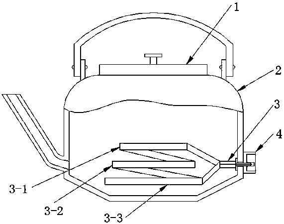
[0009] Such as figure 1 The energy-saving electric kettle shown includes a pot body 2 and a pot cover 1. An electric heating tube 3 is installed at the lower part of the inner cavity of the pot body. The position is a structure with a large top and a small bottom; the electric heating tube 3 is a spiral electric heating tube, the lower end of the spiral electric heating tube leads to a connecting end, and the upper end of the spiral electric heating tube leads to another connecting end, and is connected to the outer wall of the pot. The socket 4 is connected in cooperation, and the spiral electric heating tube is a surrounding structure of three layers of circular electric heating tubes.

[0010] Such as figure 1 As shown, in the surrounding structure of the three-layer circular electric heating tube, three layers of circular electric heating tubes are defined from the lower layer...


PUM


Abstract

The invention provides an energy-saving electric kettle. The energy-saving electric kettle comprises a kettle body and a kettle lid; an electric heating tube is installed at the lower portion of an inner cavity of the kettle body; conical surface transition is adopted for the bottom of the kettle body and the side wall of the kettle body, so that the lower portion of the kettle body is of a big-end-up structure; the electric heating tube is spiral, one connecting end is led from the lower end of the spiral electric heating tube, another connecting end is led from the upper end of the spiral electric heating tube, and the spiral electric heating tube is in matched connection with a socket arranged on the outer wall of the kettle body; the spiral electric heating tube is of an encircling structure formed by three layers of circular electric heating tube bodies. According to the energy-saving electric kettle, a traditional electric heating tube is changed into the three-layer spiral heating tube, so that the contact area of the heating tube and water is increased in the heating process, the energy consumption is reduced, the heat loss is prevented, and the heat efficiency is improved;conical surface transition is designed at the bottom of the kettle body, it is guranateed that the volume of water at the upper portion in the kettle body is larger than that of water at the lower portion in the kettle body, water at the bottom can rise easily, water at the upper portion can fall easily, and thus thermal circulation is promoted.

Description

technical field [0001] The invention belongs to the technical field of electric heating and relates to an electric kettle used for boiling water in daily life. Background technique [0002] At present, a commonly used electric kettle with a simple structure includes a pot body and a pot cover. A circle of electric heating tubes is installed at the lower part of the inner cavity of the kettle body. The inner cavity of the kettle body has a structure with a large lower area and a small upper area; When heating, the volume of cold water in the upper part of the kettle body is small, and the cold water in the upper part is not easy to drop, and the thermal cycle effect is not good, resulting in long heating time, large heat loss, and low heating efficiency. Contents of the invention [0003] In order to improve heating efficiency, make full use of heat, and reduce heating time, the present invention proposes an energy-saving electric kettle. [0004] For this reason, the tech...

Claims


Application Information

Patent Timeline
Patent Type & Authority Applications(China)
IPC IPC(8): A47J27/21A47J27/00
CPCA47J27/21016A47J27/002
Inventor 谈颜
Owner 谈颜
Why Eureka
Try Eureka