Tunable with posterior cruciate ligament reconstruction tibia positioning device on dissection force line axis extension cord

A technology of cruciate ligaments and extension wires, which is applied in the field of medical devices, can solve the problems that the anatomical structure cannot be fitted, the locator cannot reach the anatomical stop, and the locator is prone to shift and loosen, etc., so as to reduce wear and tear. The effect of "kill angle" effect

Inactive Publication Date: 2018-05-25
WEST CHINA HOSPITAL SICHUAN UNIV
View PDF17 Cites 3 Cited by
  • Summary
  • Abstract
  • Description
  • Claims
  • Application Information

AI Technical Summary

Problems solved by technology

[0004] However, the existing posterior cruciate ligament tibial locator is mainly designed for the anatomical reconstruction of the posterior cruciate ligament. The positioning tip of the tibial locator can only reach about 1cm‐1.5cm below the articular surface, and the locator cannot reach b

Method used


Image

  • Tunable with posterior cruciate ligament reconstruction tibia positioning device on dissection force line axis extension cord
  • Tunable with posterior cruciate ligament reconstruction tibia positioning device on dissection force line axis extension cord
  • Tunable with posterior cruciate ligament reconstruction tibia positioning device on dissection force line axis extension cord

Examples


Embodiment 1

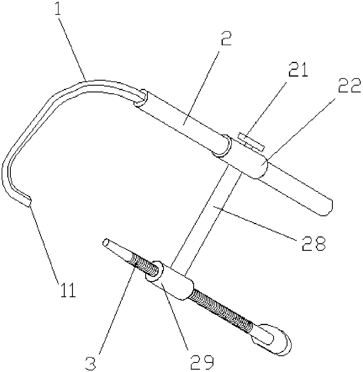
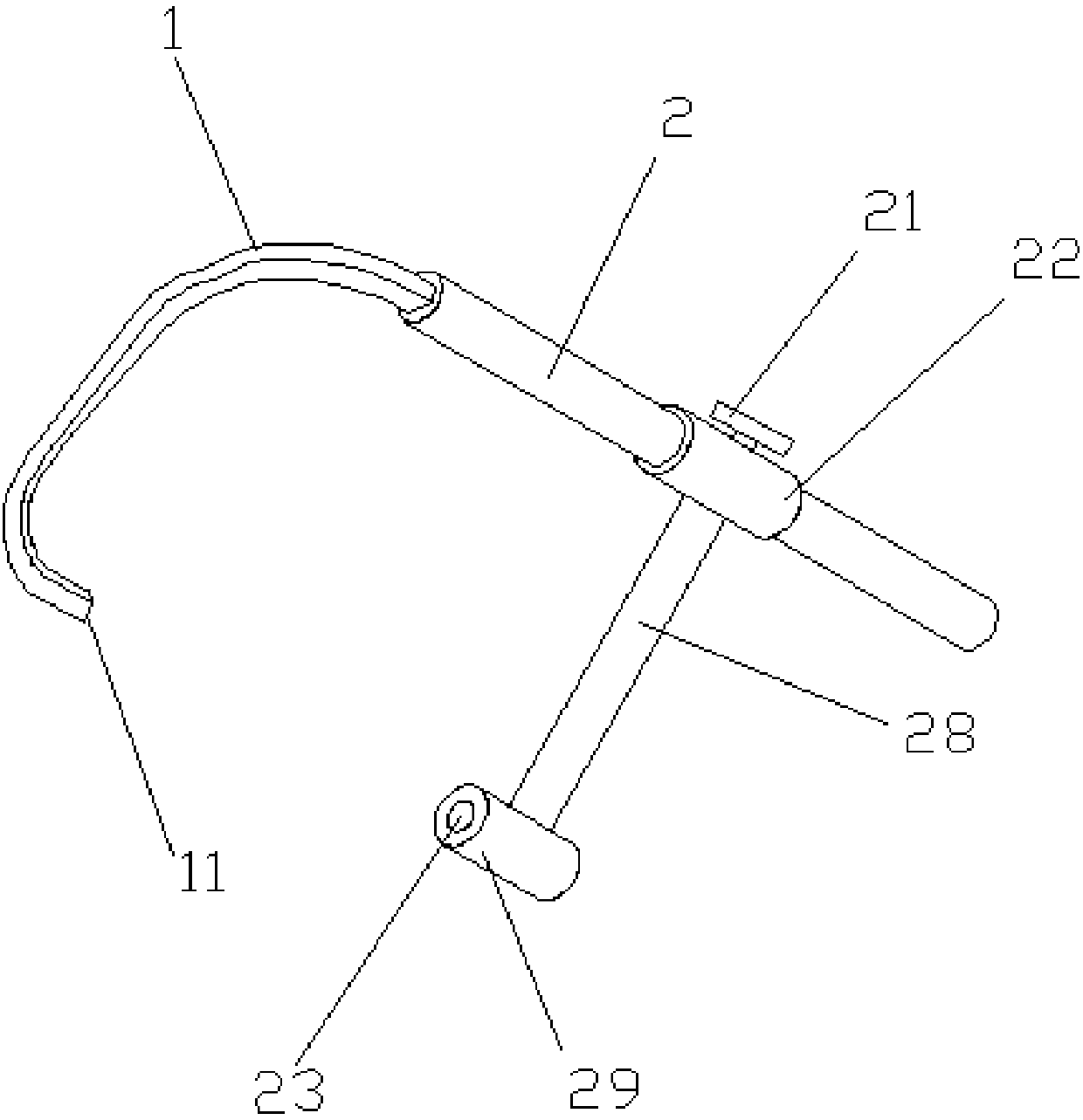
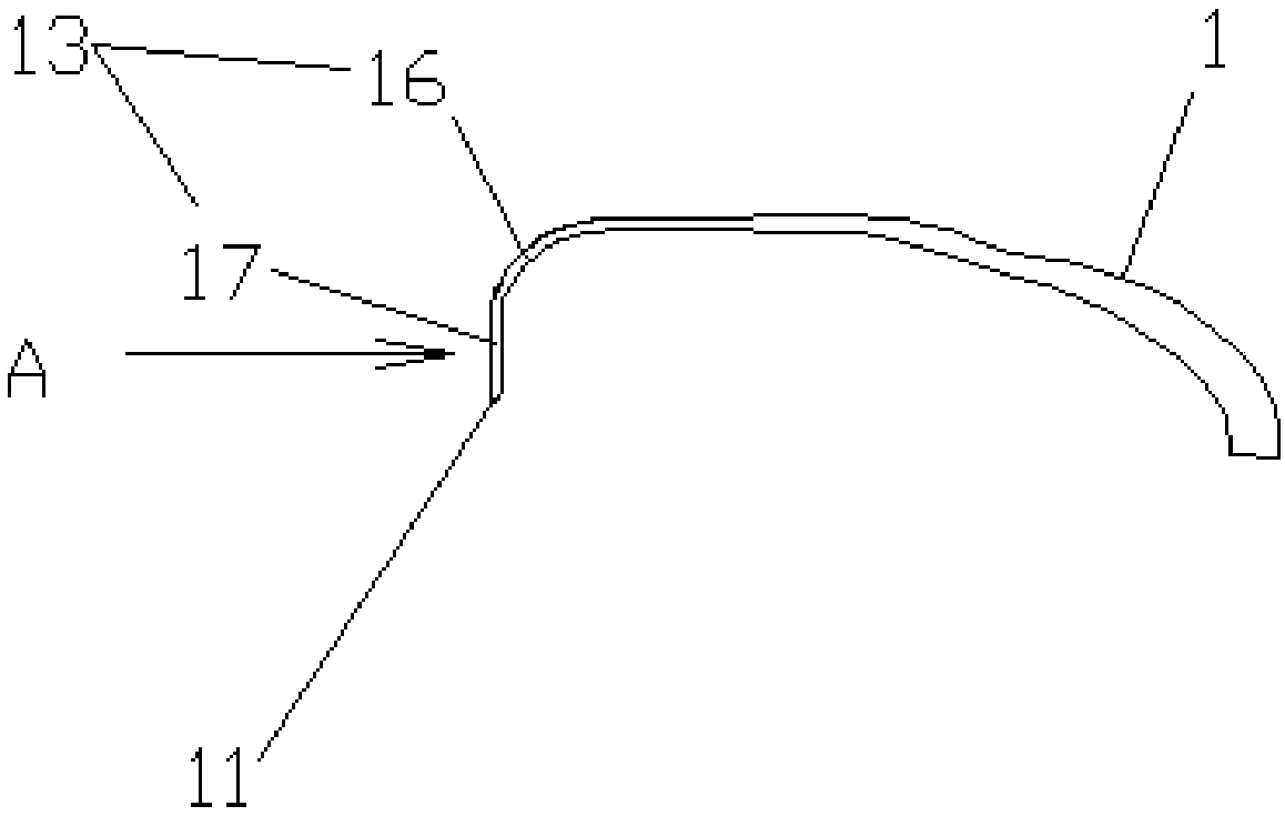
[0047] Such as figure 1 , 2 As shown in . and 3, the adjustable anatomical force axis extension line disclosed in the present embodiment is the posterior cruciate ligament reconstruction tibial positioner, comprising a positioning arm 1, a handle 2 and a guide rod 3, and the front end of the positioning arm 1 is a positioning probe hook 13 for positioning The front end of the probe hook 13 is a positioning tip 11, the rear end of the positioning arm 1 is fixedly connected to the front end of the handle 2, the handle 2 is provided with a slider 22, and the slider 22 has a locking device 21 for locking the slider 22. One end of the support rod 28 is affixed to the slide block 22, and the other end of the support rod 28 is affixed to the guide block 29, and the guide block 29 is provided with a guide hole 23; The axis of the guide hole 23 passes through the positioning tip 11 . One end of the guide rod 3 passes through the guide hole 23 and docks with the positioning tip 11 . ...

Embodiment 2

[0052] The difference between this embodiment and embodiment 1 is: as Figure 6 , 7 As shown, the guide block 29 is provided with a slot 25, and the insert block 24 is inserted in the slot 25, and the guide hole 23 is arranged on the insert block 24.

[0053] Such as Figure 8 , 9 As shown, the guide hole 23 in the insert block 24 is not offset, and the insert block 24 of this structure is adapted to the positioning arm 1 whose positioning tip 11 is not sideways. Such as Figure 10 , 11 As shown, the guide hole 23 in the insert block 24 is left biased, and the insert block 24 of this structure and Figure 5 The positioning tip 11 in the adapter is adapted. Such as Figure 12 , 13 As shown, the guide hole 23 in the insert block 24 is biased to the right, and the insert block 24 of this structure and Figure 4 The positioning tip 11 in the adapter is adapted.

[0054] There is a locking mechanism for locking the plug 24 on the guide block 29. The locking mechanism incl...

Embodiment 3

[0057] The difference between this embodiment and embodiment 2 is: as Figure 14 , 15 As shown, the positioning arm 1 is divided into two parts, one part is a positioning probe hook 13 including a positioning tip 11, and the two parts are screwed together. The rear end of the positioning probe hook 13 has an extended connecting arm 14, and the connecting arm 14 has external threads; the front end of the other part corresponding to it has an adapted threaded hole 15.

[0058] Such as Figure 16 As shown, the positioning probe hook with the positioning tip 11 not sideways, which is the same as Figure 8 and 9 Insert block 24 fits as shown; as Figure 17 As shown, the positioning probing hook with the positioning tip 11 to the left is similar to Figure 10 and 11 Insert block 24 shown fits. Such as Figure 18 As shown, the positioning probing hook with the positioning tip 11 to the right, which is the same as Figure 12 and 13 Insert block 24 shown fits. In this embodi...


PUM


Abstract

The invention relates to a tunable with posterior cruciate ligament reconstruction tibia positioning device on a dissection force line axis extension cord. The tunable posterior cruciate ligament reconstruction tibia positioning device includes a positioning arm and a handle, the rear end of the positioning arm is fixedly connected with the front end of the handle, a sliding block is arranged on the handle, a locking device for locking the sliding block is arranged on the sliding block, one end of a support rod is fixedly connected with the sliding block, the other end of the support rod is fixedly connected with a guide block, and a guide hole is formed in the guide block; a positioning tip at the front end of the positioning arm inclines to the left or the right, and the axis of the guide hole penetrates through the positioning tip. According to the tunable posterior cruciate ligament reconstruction tibia positioning device on the dissection force line axis extension cord, the positioning tip inclines to the exterior, and therefore the positioning tip can be located on a slope groove on the posterior cruciate ligament dissection force line axis extension cord behind the proximaltibia; meanwhile, the positioning tip deforms along the slope groove, passes through a posterior cruciate ligament stop and arrives at the inner side of the fossa intercondyloidea, an acute angle formed by a transplant and a tibia tunnel is successfully converted into two obtuse angles, pressure on the tibia tunnel and pressure on part of the transplant are reduced, abrasion caused by the edge ofthe tibia tunnel to the transplant is reduced, and a killer turn effect is reduced.

Description

technical field [0001] The invention relates to the technical field of medical devices, in particular to a tibial tunnel locator that can be adjusted on the extension line of the anatomical force line axis for reconstruction of the posterior cruciate ligament. Background technique [0002] Arthroscopic reconstruction of the posterior cruciate ligament is an effective method for the treatment of posterior cruciate ligament injuries, but there is still a big debate in the field of sports medicine, because the posterior cruciate ligament reconstruction has not achieved as effective and constant clinical effect as the anterior cruciate ligament reconstruction, relatively high failure rate. The most common technique used for PCL reconstruction today is the "transtibial" tunneling technique, through which a graft is introduced and secured within a bone tunnel. [0003] Patent document CN202604902U discloses a guider for reconstructing the posterior cruciate ligament combined with...

Claims


Application Information

Patent Timeline
IPC IPC(8): A61B17/56A61B90/11A61B17/90
CPCA61B17/88A61B2017/564A61B90/11A61B17/90
Inventor 李箭王志强熊燕陈刚李棋唐新付维力张钟蒋海
Owner WEST CHINA HOSPITAL SICHUAN UNIV
Why Eureka
Try Eureka