Woodworking square hole drill

A square hole drilling and woodworking technology, applied to wood processing equipment, drilling machines, manufacturing tools, etc., can solve the problems of low work efficiency, large vibration, and inapplicability to mass production, and achieve high production efficiency and reduce shaking. Effect

Inactive Publication Date: 2018-05-25
天津千艺达建筑工程有限公司
View PDF5 Cites 0 Cited by
  • Summary
  • Abstract
  • Description
  • Claims
  • Application Information

AI Technical Summary

Problems solved by technology

Such grooves often have low precision and rough groove walls. To dig out high-quality grooves requires experienced staff to work, the work efficiency is low, and the technical level of the personnel is required to be high. It is not suitable for large-scale production. Production
[0003] In the square hole drill in the prior art, the gap between the drill core and the chip hole of the drill sleeve is too large, the vibration is too large during use, and the hole diameter is too large to meet the requirements; Chip speed is slow, affecting normal work and use

Method used


Image

  • Woodworking square hole drill
  • Woodworking square hole drill

Examples


Embodiment Construction

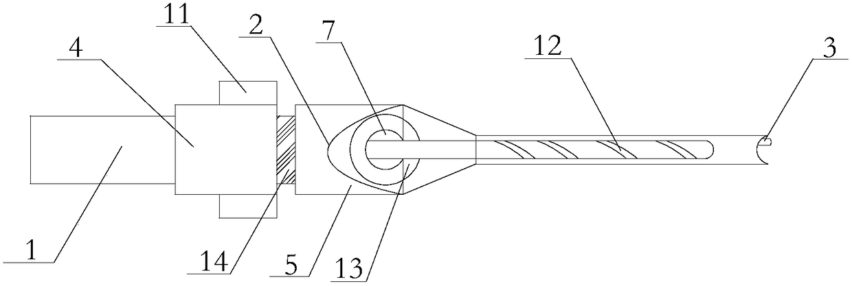
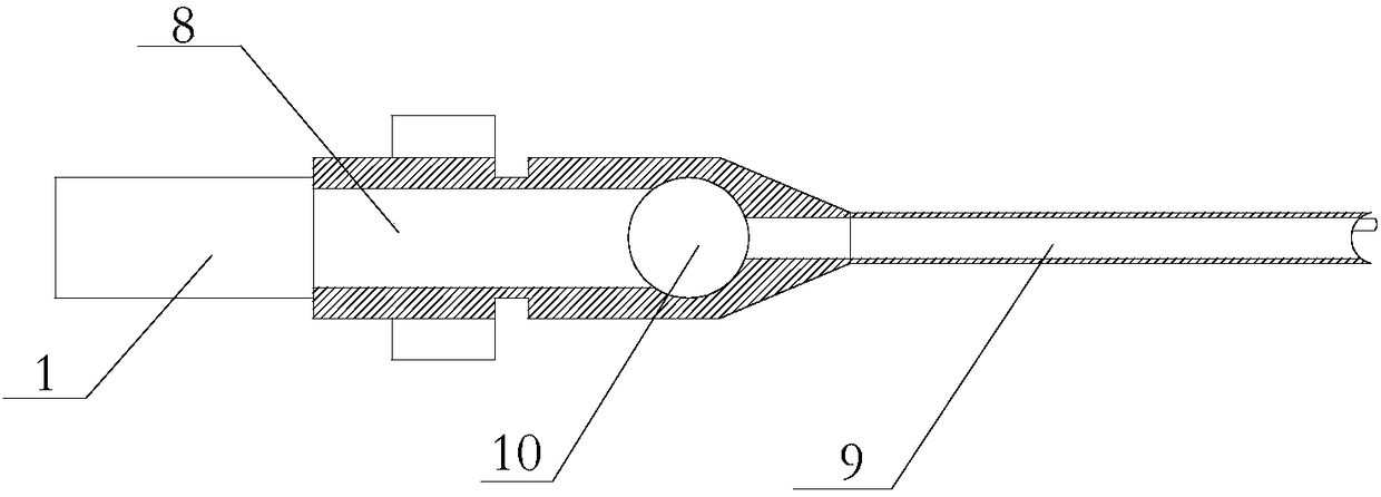
[0018] The present invention will be described in detail below in conjunction with the accompanying drawings.

[0019] Such as figure 1 , figure 2 As shown, a woodworking square hole drill of the present invention comprises a drill core 1, a drill sleeve 2, and a drill tip 3. The outer cover of the drill core 1 is provided with a drill sleeve 2, and the front end of the drill core 1 is provided with a drill tip. 3. The drill sleeve 2 includes a clamping part 4, a guide part 5, a chip removal groove 6, a chip removal hole I7, a drill bit installation groove I8, a drill bit installation groove II9, and a chip removal hole II10. The guide part 5 is set on the clamp One side of the holding part 4, the two sides of the holding part 4 are provided with a suction fan 11, the chip removal hole I7 is set on the outer wall of the guide part 5, and the chip removal groove 6 runs through the guide part 5 and the chip removal hole I7, the center of the clamping part 4 is provided with a...


PUM


Abstract

The invention provides a woodworking square hole drill, wherein a drill sleeve is arranged on the outer portion of a drill core in a sleeved manner, the front end of the drill core is provided with adrill tip, the drill sleeve comprises a clamping part, a guide part, a sawdust discharge groove, a sawdust discharge hole I, a drill bit installation groove I, a drill bit installation groove II and asawdust discharge hole II, wherein the guide part is arranged on one side of the clamping part, both sides of the clamping part are provided with wind suction devices, the sawdust discharge hole I isarranged on the outer wall of the guide part, the sawdust discharge groove penetrates through the guide part and the sawdust discharge hole I, the center of the clamping part is provided with the drill bit installation groove I, the center of the guide part is provided with the drill bit installation groove II, the outer side of the guide part is provided with the sawdust discharge hole II penetrating through the guide part, the drill core is provided with a spiral sawdust outlet groove, the sawdust discharge hole I is provided with an elastic position limiting member matched with the drill core, and the outer side of the clamping part is provided with a snapping groove. According to the present invention, under the co-action of the sawdust discharge groove and the sawdust discharge holes, the wind suction devices rapidly apply the adsorption force on the sawdust, the broken sawdust generated by the drilling is rapidly discharged, and the elastic position limiting member is arranged on the periphery of the drill core so as to stabilize the drill core and reduce the shaking degree.

Description

technical field [0001] The invention belongs to the technical field of wood processing equipment, in particular to a woodworking square hole drilling machine. Background technique [0002] In order to connect two pieces of wood at a certain angle, carpenters generally use the method of tenon joint, which requires digging rectangular grooves in the wood. In general, the square chisel is used to dig out the groove bit by bit, and it is shaped after careful correction. Such grooves often have low precision and rough groove walls. To dig out high-quality grooves requires experienced staff to work, the work efficiency is low, and the technical level of the personnel is required to be high. It is not suitable for large-scale production. Production. [0003] In the square hole drill in the prior art, the gap between the drill core and the chip hole of the drill sleeve is too large, the vibration is too large during use, and the hole diameter is too large to meet the requirements;...

Claims


Application Information

Patent Timeline
Patent Type & Authority Applications(China)
IPC IPC(8): B27C3/00B27F5/02B27G3/00
CPCB27C3/00B27F5/02B27G3/00
Inventor 宋家宾
Owner 天津千艺达建筑工程有限公司
Why Eureka
Try Eureka