Fluid heat exchange assembly and vehicle heat management system

A technology for heat exchange components and fluids, which is applied in vehicle components, component optimization, and air handling equipment. The effect of piping layout, reducing heat waste

Active Publication Date: 2018-05-25
HANGZHOU SANHUA RES INST CO LTD
View PDF9 Cites 15 Cited by
  • Summary
  • Abstract
  • Description
  • Claims
  • Application Information

AI Technical Summary

Problems solved by technology

However, the components used in the current vehicle thermal management system are generally installed separately from the entire vehicle. The installation space of each component takes up a lot and requires a lot of pipelines, which easily makes the layout structure chaotic.

Method used


Image

  • Fluid heat exchange assembly and vehicle heat management system
  • Fluid heat exchange assembly and vehicle heat management system
  • Fluid heat exchange assembly and vehicle heat management system

Examples


Embodiment Construction

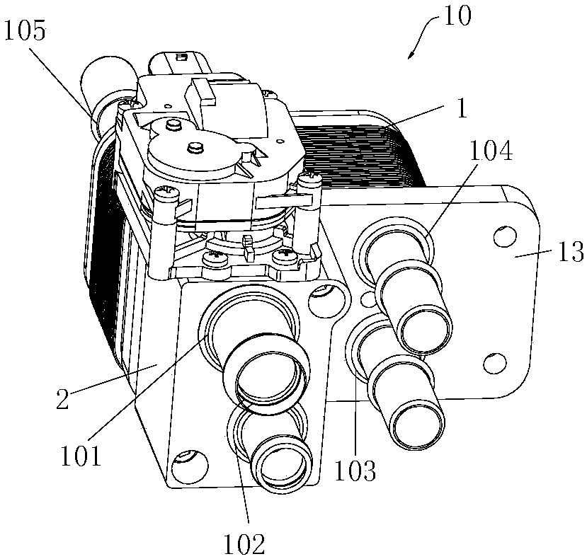
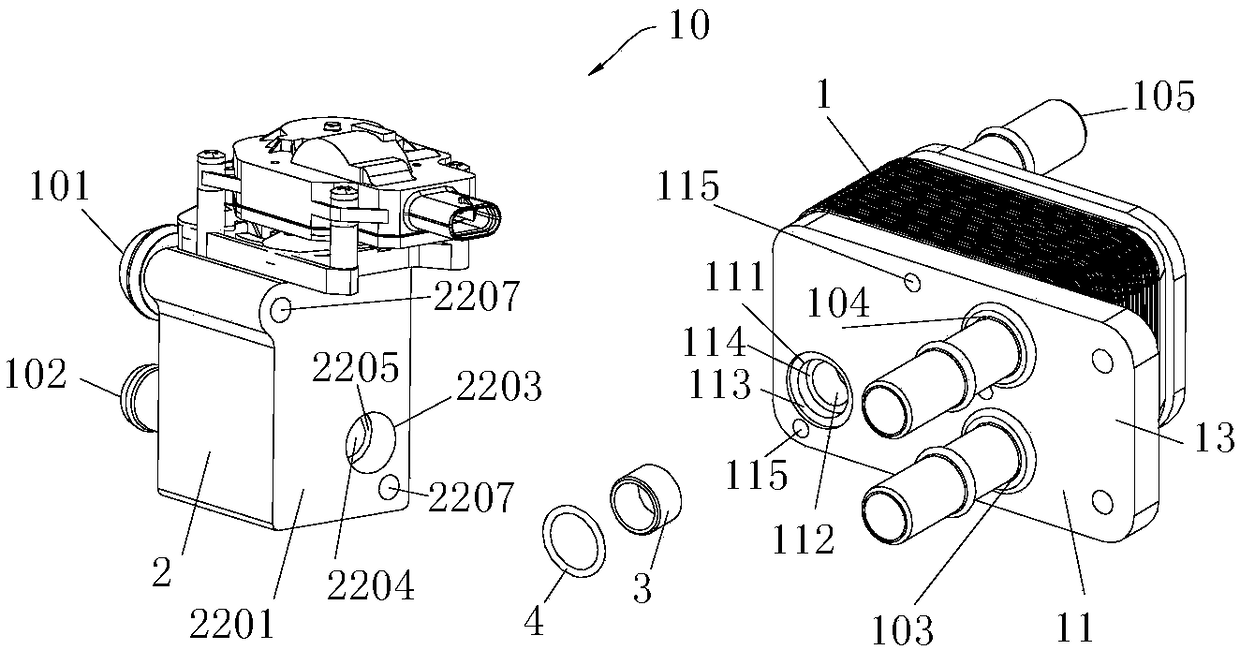
[0035] Reference figure 1 , figure 1 A schematic diagram of the fluid heat exchange assembly 10 is shown. The fluid heat exchange assembly 10 includes at least a first external interface 101, a second external interface 102, and a third external interface 103. The fluid heat exchange assembly 10 includes a fluid heat exchange module 1 and a fluid conduction Module 2, the fluid conduction module 2 is provided with a first external interface 101 and a second external interface 102, and the fluid heat exchange module 1 is provided with a third external interface 103. In this article, the external interface is located at the port of the channel of the fluid heat exchange component. In the figure, when the external interface is not visible, in order to facilitate the location of the external interface, the position of the external interface may refer to the external interface connected to the external interface. Take over.

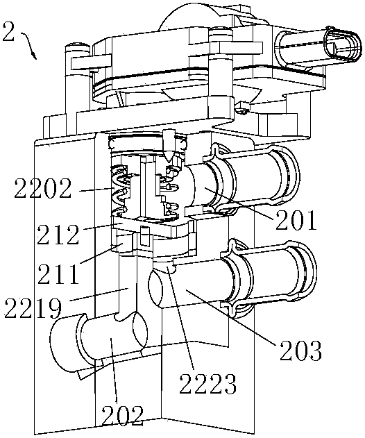
[0036] Reference image 3 The fluid conduction module 2 incl...


PUM


Abstract

The invention discloses a fluid heat exchange assembly and a vehicle heat management system. The fluid heat exchange assembly comprises a fluid conduction module and a fluid heat exchange module. Thefluid conduction module comprises a base portion, a first body portion and a second body portion. The base portion comprises a first installation cavity and a second installation cavity. At least partof the first body portion is located in the first installation cavity. At least part of the second body portion is located in the second installation cavity. The base portion comprises a first path,a second path, a third path, a fourth path, a fifth path and a sixth path. The first path communicates with at least one of the second path and the third path. The fourth path communicates with at least one of the fifth path and the sixth path. A first fluid heat exchange channel communicates with the second path. A second fluid heat exchange channel communicates with the fifth path. According tothe fluid heat exchange assembly, the line routing is reduced, and the overall structure is compact.

Description

Technical field [0001] The invention relates to the field of fluid heat exchange and vehicle thermal management systems. Background technique [0002] The vehicle thermal management system is a system that coordinates the relationship between heat, engine or battery and the vehicle from the perspective of system integration and overall, and adopts comprehensive means to control and optimize heat transfer. It can automatically adjust according to driving conditions and environmental conditions. Cooling intensity to ensure that the cooled object works in the best temperature range, thereby optimizing the environmental performance and energy saving effect of the whole vehicle, and improving the safety of the vehicle and driving comfort. However, the components used in the current vehicle thermal management system are generally installed separately from the entire vehicle. Each component takes up a large installation space and requires a lot of pipelines, which easily makes the layou...

Claims


Application Information

Patent Timeline
Patent Type & Authority Applications(China)
IPC IPC(8): B60H1/00B60H1/32
CPCB60H1/00271B60H1/00278B60H1/32B60H2001/00307Y02T10/88B60H1/3229B60H1/00485
Inventor 不公告发明人
Owner HANGZHOU SANHUA RES INST CO LTD
Why Eureka
Try Eureka