Holding device

A technology for clamping wheels and seats, applied in conveyors, manipulators, chucks, etc., can solve the problems of easily damaged workpiece surface, weak structure of end holders, etc., and achieves the effect of compact structure, balanced strength and strong reliability.

Pending Publication Date: 2018-05-25
汉尼康自动化科技(苏州)有限公司
View PDF8 Cites 3 Cited by
  • Summary
  • Abstract
  • Description
  • Claims
  • Application Information

AI Technical Summary

Problems solved by technology

[0004] In view of this, the present invention provides an end holder, which solves the problem that the existing end holder has a weak structure and is easy to damage the surface of the workpiece

Method used


Image

  • Holding device
  • Holding device
  • Holding device

Examples


Embodiment

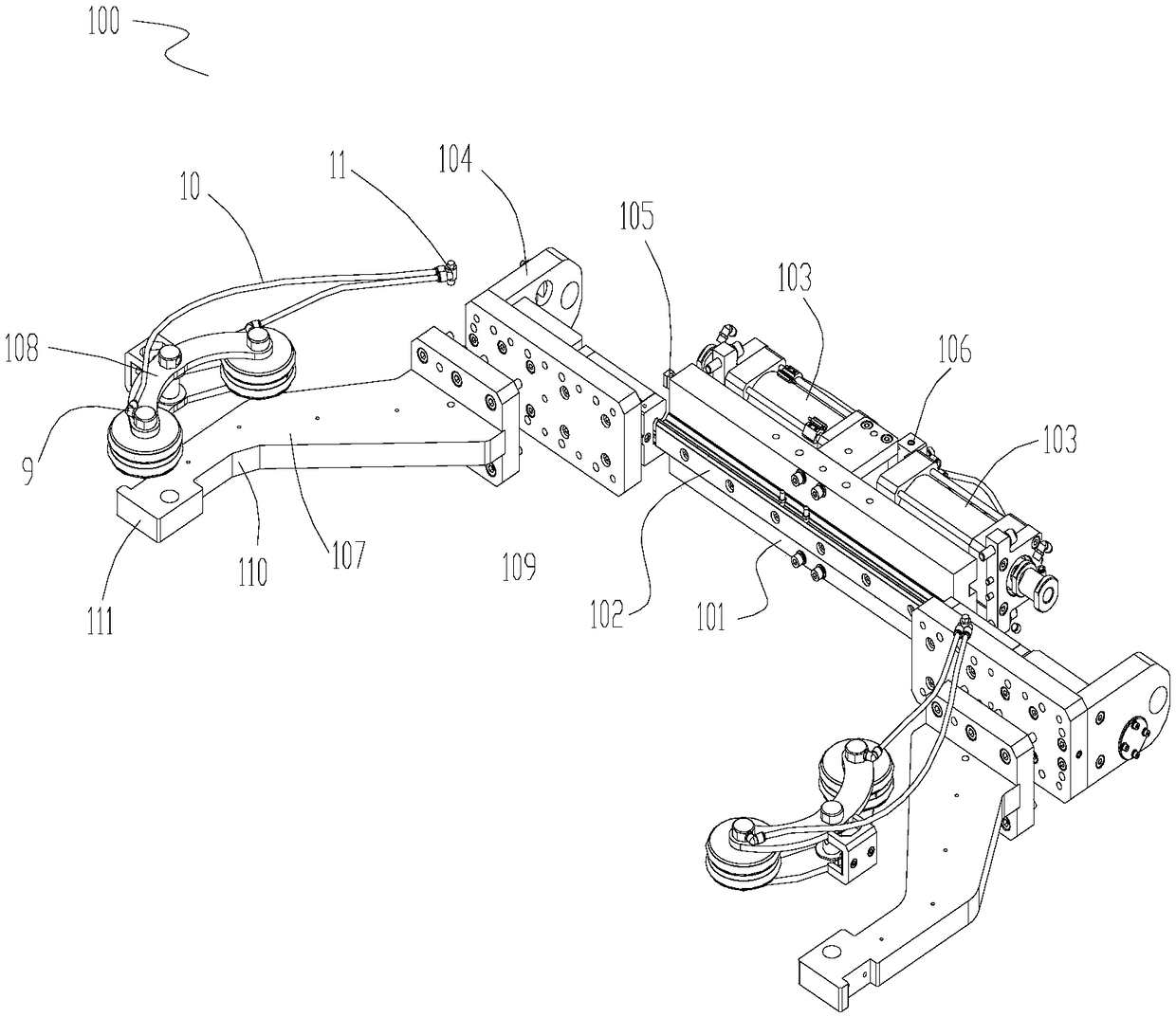
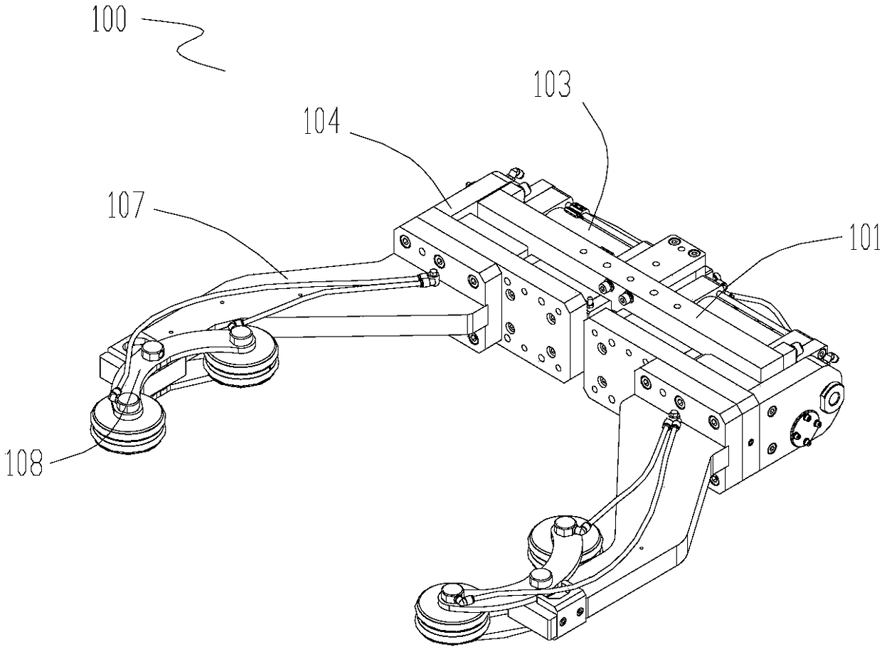
[0018] Please also refer to Figures 1 to 2 , an end holder 100, comprising a seat body 101, a slide rail 102 is provided on one side of the seat body 101, and two oppositely arranged cylinders 103 are provided on the other side.

[0019] Two slide assemblies 104 are mounted on the slide rail 102 and can move synchronously along the slide rail under the action of the cylinder 103 . The base body 101 is further provided with racks 105 fixedly connected with the two sliding assemblies 104 respectively. A valve guide assembly 106 is also arranged on the seat body 101 .

[0020] An arm assembly 107 is fixed on the sliding assembly 104 , and a clamping finger 108 is also provided at the free end of the arm assembly 107 .

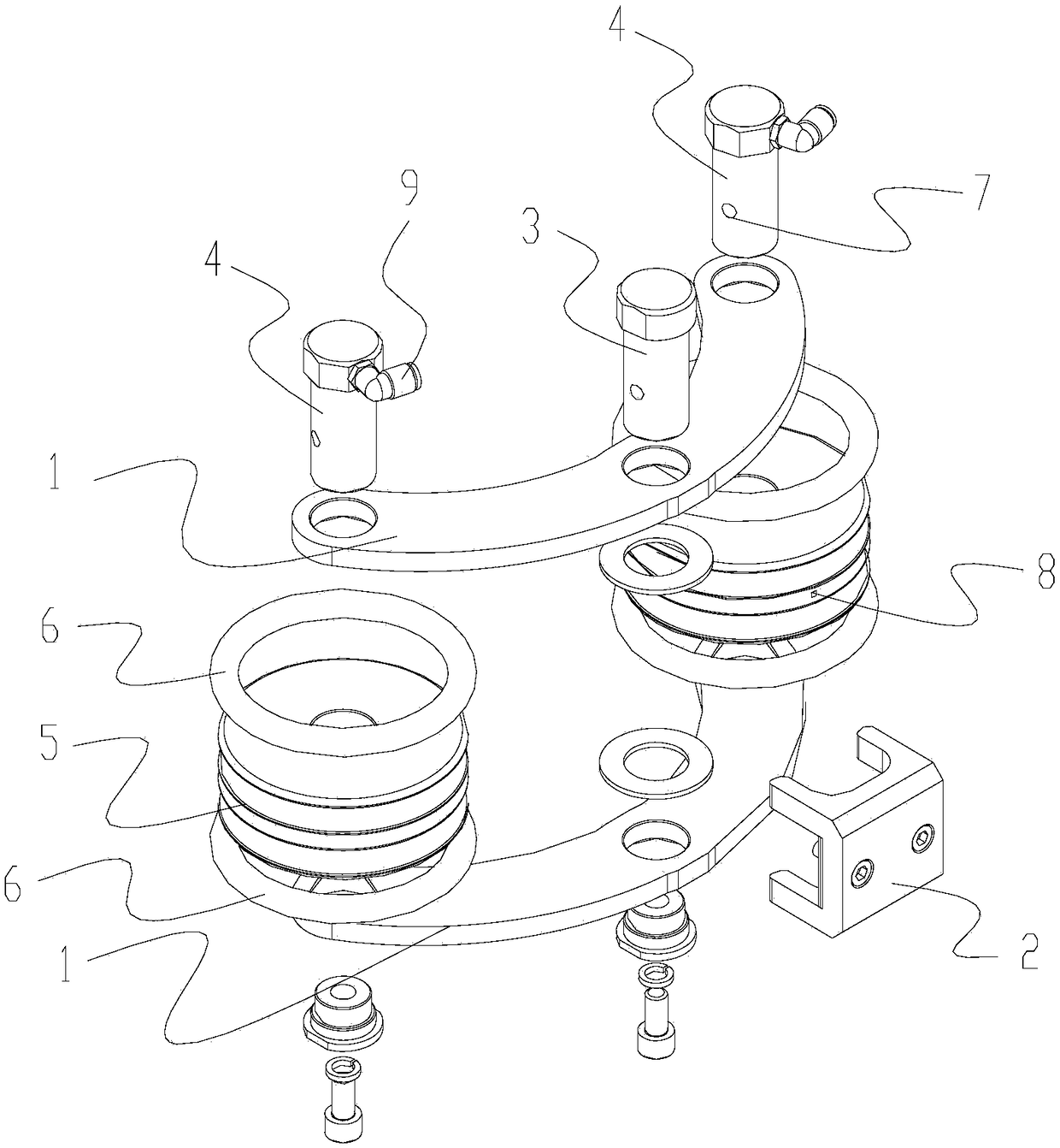
[0021] The arm assembly 107 has: a fixing portion 109 connected to the slider assembly 104 , and a middle bending portion 110 . The connecting block 2 for clamping the finger 108 is fixed on the free end 111 of the arm assembly, and one of the clamping wheels ...


PUM


Abstract

The invention discloses a holding device. The holding device comprises a seat body, wherein a sliding rail is arranged on one side of the seat body, two opposite air cylinders are arranged on the other side of the seat body, two sliding assemblies which can synchronously move along the sliding rail under the action of the air cylinders are installed on the sliding rail, and racks which are fixedlyconnected with the two sliding assemblies are arranged on the seat body; arm assemblies are fixed to the sliding assemblies, and clamping fingers are arranged on the free ends of the arm assemblies;and the clamping fingers include two bending plates and a connecting block which are arranged across the two bending plates, a fixed shaft is arranged in the middle of the two arc-shaped bending plates, connecting shafts are respectively arranged on both ends of the bending plates, and clamping wheels are installed on the connecting shafts. According to the holding device, the sliding assemblies are driven to move along the sliding rail by double air cylinders, and the force balance of the two arm assemblies during clamping is guaranteed by utilizing the two racks. The holding device has the advantages of compact structure, firmness in clamping, low manufacturing cost and high reliability and has certain market prospects.

Description

technical field [0001] The invention relates to a linked end holder for clamping an automobile wheel hub, and belongs to the technical field of clamping. Background technique [0002] In the manufacturing process of aluminum wheels, material transfer between various processes is required. The traditional material transfer is generally completed through the connecting rod end holder. This technology drives the connecting rod through the cylinder and uses the principle of mechanical control to realize the control of the product. Clamping, to complete the process of fully automatic entry of products from the preheating furnace to the spinning machine, but because the structure of the link-type end holder needs to be equipped with a large number of parts, its economic cost is relatively high; and its cumulative tolerance is large during operation , leading to low positioning accuracy. [0003] For example, Chinese patent application No. 201420275738.4 discloses a linkage type e...

Claims


Application Information

Patent Timeline
Patent Type & Authority Applications(China)
IPC IPC(8): B65G47/90B25J15/08
CPCB65G47/90B25J15/08B65G2201/0214
Inventor 喻泽军张峰张国林郭西讲
Owner 汉尼康自动化科技(苏州)有限公司
Why Eureka
Try Eureka