
Device for removing aqueous phase from loaded organic phase

A technology for removing water and organic phases, applied in the direction of improving process efficiency, etc., can solve the problems of reduced compactness, economic loss, and incomplete clarification of copper electrodeposited

Active Publication Date: 2018-05-25
GEM JIANGSU COBALT IND CO LTD
View PDF12 Cites 0 Cited by
  • Summary
  • Abstract
  • Description
  • Claims
  • Application Information

AI Technical Summary

Problems solved by technology

[0003] The extraction process is a continuous operation process. The loaded organic obtained in each extraction process contains a certain amount of water phase due to the "water-in-oil" phenomenon. In general, the volume ratio of the water phase to the organic phase is about 0.1~ 0.2:100, the composition of this part of the water phase is equal to the composition of the pre-extraction liquid, and will enter the back-extraction process together with the organic load, and will be mixed into the back-extraction liquid, which will increase the content of harmful impurities in the back-extraction liquid and directly affect the extraction process. The quality of the extract
Especially for the extraction of copper, loading the aqueous phase in the organic phase will not only increase the chloride ion content of the stripped liquid, affect the quality of the electrodeposited copper, and reduce the density of the electrodeposited copper, but also cause the oxidizing substances in the aqueous phase to increase the concentration of the stripped copper. It is carried out under high acid and sulfuric acid content of 180-200g / l. During the stripping process, the potential of the solution will become higher, causing the copper extractant to be oxidized and degraded, commonly known as "poisoning". In severe cases, the extractant will completely fail and have to be replaced. New extractant, causing serious economic losses

Method used


Image

  • Device for removing aqueous phase from loaded organic phase

Examples


Embodiment Construction

[0019] In order to make the object, technical solution and advantages of the present invention clearer, the present invention will be further described in detail below in conjunction with the accompanying drawings and embodiments. It should be understood that the specific embodiments described here are only used to explain the present invention, not to limit the present invention.

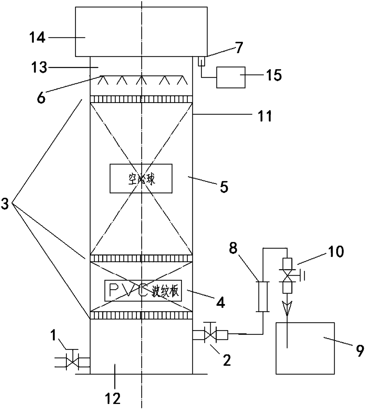
[0020] Embodiments of the present invention provide a device for removing the water phase from the loaded organic phase, such as figure 1 As shown, it includes a cylindrical body 11. The inside of the body 11 is sequentially provided with a feed area 12, a PVC corrugated plate 4, a hollow ball area 5, and a flushing area 13. A cylindrical body is provided above the body. Separation zone 14, the diameter of the separation zone 14 is greater than the diameter of the body 11, the feed zone 12, the PVC corrugated plate 4, the hollow ball zone 5 and the flushing zone 13 are separated by the grid plate 3...


PUM

PropertyMeasurementUnit
diameteraaaaaaaaaa

Abstract

The invention discloses a device for removing an aqueous phase from a loaded organic phase. The device comprises a cylindrical body. A feeding region, a PVC corrugated plate, a hollow sphere and a washing region are sequentially arranged inside the body from bottom to top. A cylindrical separation region is arranged above the body. The diameter of the separation region is larger than that of the body. The loaded organic phase flows inside the body from the bottom to the upper side, and tiny aqueous phase droplets generated in the loaded organic phase due to the phenomenon of 'water in oil' canbe collected through treatment of the PVC corrugated plate and a hollow sphere dielectric layer. The collected aqueous phase is settled to the bottom in a downward mode and then enters an aqueous phase groove from an aqueous phase outlet, and the aqueous phase returns to feed liquid before the extraction section. The organic phase moves upwards to the separation region and then enters an organicstorage groove from an overflow port, and thus the purpose of removing the aqueous phase from the loaded organic phase is achieved.

Description

technical field [0001] The invention belongs to the technical field of hydrometallurgy technology, and in particular relates to a device for removing a water phase from a loaded organic phase. Background technique [0002] When using hydrocobalt ore and cobalt intermediates mainly containing cobalt hydroxide and cobalt carbonate for hydrometallurgy, the cobalt solution after leaching and removing iron needs to be deeply purified through the extraction process of copper extraction, P204 extraction, and P507 extraction. [0003] The extraction process is a continuous operation process. The loaded organic obtained in each extraction process contains a certain amount of water phase due to the "water-in-oil" phenomenon. In general, the volume ratio of the water phase to the organic phase is about 0.1~ 0.2:100, the composition of this part of the water phase is equal to the composition of the pre-extraction liquid, and will enter the back-extraction process together with the organ...

Claims


Application Information

Patent Timeline
Patent Type & Authority Applications(China)
IPC IPC(8): C22B3/02C22B3/26
CPCC22B3/02C22B3/26Y02P10/20
Inventor 李炳忠仲扣成伍一根杜长福叶圣毅
Owner GEM JIANGSU COBALT IND CO LTD
Learn More