Material transportation guide rail

A guide rail and material technology, applied in the field of guide rail, can solve the problems of low work efficiency, high work intensity, wear and tear of transport chain car, etc., and achieve the effect of smooth connection, convenient processing and simple structure

Inactive Publication Date: 2018-05-25
晋中贝斯特机械制造有限公司
View PDF1 Cites 0 Cited by
  • Summary
  • Abstract
  • Description
  • Claims
  • Application Information

AI Technical Summary

Problems solved by technology

The materials that need to be transported in the textile industry include cotton bales, rovings, spun yarns, bobbins, roving bobbins, spun bobbins, etc. Nowadays, most of the rovings and roving bobbins in textile factories are transported by manual trolleys, which has high work intensity and low work efficiency.
With the continuous progress and development of science and technology, in recent years, textile mills are also gradually realizing unmanned production, especially the rail transportation of materials between various production processes, but most of the roving transport guide rails in existing textile mills are bent steel plates Forming or aluminum alloy cold drawing forming, the processing technology of steel plate bending forming cannot be guaranteed, and it is easy to cause the wear and tear of the transport chain car and the phenomenon of jamming. The announcement number is: CN202898643U patent discloses a roving transport guide rail formed by cold drawing of aluminum alloy , the guide rail is a semi-sealed type, which is easy to accumulate flying flowers and cannot be cleaned, which may easily cause the chain car to be stuck

Method used


Image

  • Material transportation guide rail

Examples


Embodiment 1

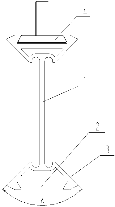
[0015] A material transportation guide rail, comprising a guide rail body 1, the guide rail body 1 is a "I" shaped symmetrical structure, the guide rail body 1 is a one-time molding structure, the upper and lower ends of the guide rail body are provided with installation grooves 2, the installation grooves 2 are trapezoidal grooves, and the installation grooves 2 is provided with T-shaped connecting bolts 4, and guide rail surfaces 3 are provided on the left and right sides of the guide rail body 1, and the angle between the two guide rail surfaces is 30°.

[0016] The guide rail body is fixed by T-shaped connecting bolts, and because of its one-time molding, the sealing performance is better.

Embodiment 2

[0018] A material transportation guide rail, comprising a guide rail body 1, the guide rail body 1 is a "I" shaped symmetrical structure, the guide rail body 1 is a one-time molding structure, the upper and lower ends of the guide rail body are provided with installation grooves 2, the installation grooves 2 are trapezoidal grooves, and the installation grooves 2 is provided with T-shaped connecting bolts 4, and guide rail surfaces 3 are provided on the left and right sides of the guide rail body 1, and the angle between the two guide rail surfaces is 45°.

[0019] The guide rail body is fixed by T-shaped connecting bolts, and because of its one-time molding, the sealing performance is better.

Embodiment 3

[0021] A material transportation guide rail, comprising a guide rail body 1, the guide rail body 1 is a "I" shaped symmetrical structure, the guide rail body 1 is a one-time molding structure, the upper and lower ends of the guide rail body are provided with installation grooves 2, the installation grooves 2 are trapezoidal grooves, and the installation grooves 2 is provided with T-shaped connecting bolts 4, and guide rail surfaces 3 are provided on the left and right sides of the guide rail body 1, and the angle between the two guide rail surfaces is 90°.

[0022] The guide rail body is fixed by T-shaped connecting bolts, and because of its one-time molding, the sealing performance is better.


PUM

PropertyMeasurementUnit
angleaaaaaaaaaa
angleaaaaaaaaaa
angleaaaaaaaaaa

Abstract

Disclosed is a material transportation guide rail. The guide rail comprises a guide rail body and is characterized in that the guide rail body is of an I-shaped symmetrical structure which is integrally formed, the upper and lower end surfaces of the guide rail body are provided with mounting grooves, and the included angle of the left and right guide rail surfaces of the guide rail body is 30-150degrees. The material transportation guide rail is simple in structure, convenient to process, smooth in connection, easy to clean and good in sealing effect.

Description

technical field [0001] The invention relates to a guide rail, in particular to a material transport guide rail used in the field of textile processing. Background technique [0002] Material transportation exists in all walks of life to realize the circulation and conversion of materials between production processes in various industries. The materials that need to be transported in the textile industry include cotton bales, rovings, spun yarns, bobbins, roving bobbins, spun bobbins, etc. Nowadays, most of the rovings and roving bobbins in textile factories are transported by manual trolleys, which has high work intensity and low work efficiency. With the continuous progress and development of science and technology, in recent years, textile factories have also gradually realized unmanned production, especially the rail transportation of materials between various production processes, but most of the roving transportation guide rails in existing textile factories are bent st...

Claims


Application Information

Patent Timeline
Patent Type & Authority Applications(China)
IPC IPC(8): D01H13/04
CPCD01H13/04
Inventor 宋立平田素云桑建中张斌
Owner 晋中贝斯特机械制造有限公司
Why Eureka
Try Eureka