Automatic winding welding device

A welding equipment and automatic winding technology, applied in coil manufacturing, electrical components, inductor/transformer/magnet manufacturing, etc., can solve the problems of unguaranteed quality, easy damage to inductor coils, affecting winding efficiency, etc., to achieve intelligent Counting statistics, improving accuracy and efficiency, and improving the effect of winding efficiency

Active Publication Date: 2018-05-25
东莞市高东电子科技有限公司
View PDF7 Cites 9 Cited by
  • Summary
  • Abstract
  • Description
  • Claims
  • Application Information

AI Technical Summary

Problems solved by technology

[0002] The inductance coil is a device that uses the principle of electromagnetic induction to work. It is made of wires that are wound around the insulating tube one by one. The wires are insulated from each other, and the insulating tube can be hollow or contain iron cores or magnetic powder cores. At present, most of the induction coil winding and welding equipment is completed by manual hooking using magnetic rings, etc., or the assembled traditional inductor is completed by semi-automatic CNC winding equipment. Complete, these winding devices belong to single-axis winding, which is not only inefficient, but also the bulk form of the output coil is not conducive to the automation of subsequent processes, thus affecting the efficiency of winding, and the welding work cannot be completed automatically. At the same time, the inductance coil is in the When in use, it is generally welded on the circuit board through its pins. Therefore, to make the coil inductor pins solderable, it is first necessary to peel off the insulating varnish on the coil inductor pins. The traditional paint stripping is easy to damage the inductor coil. There is no guarantee of quality, and some use strong corrosive agents to corrode the paint. This method also has a certain degree of damage to the inductance coil, and the defect rate is high. Therefore, an automatic winding welding equipment is urgently needed to meet people's needs.

Method used


Image

  • Automatic winding welding device
  • Automatic winding welding device
  • Automatic winding welding device

Examples


Embodiment Construction

[0016] The following will clearly and completely describe the technical solutions in the embodiments of the present invention with reference to the accompanying drawings in the embodiments of the present invention. Obviously, the described embodiments are only some, not all, embodiments of the present invention. Based on the embodiments of the present invention, all other embodiments obtained by persons of ordinary skill in the art without making creative efforts belong to the protection scope of the present invention.

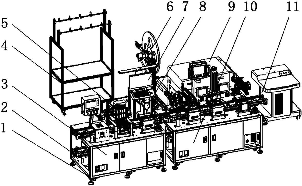
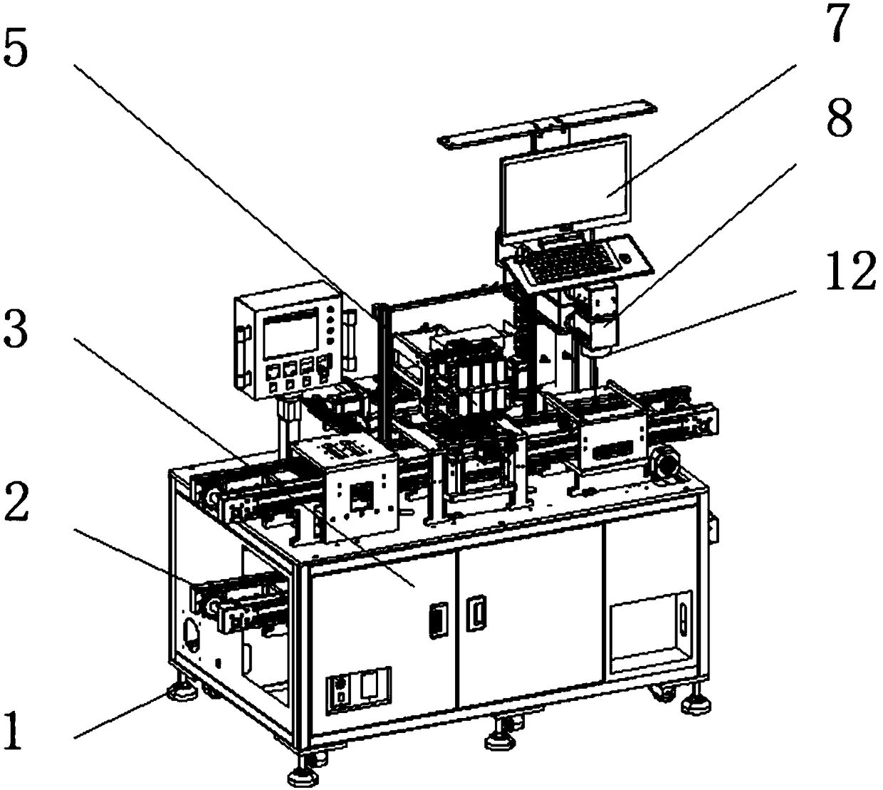
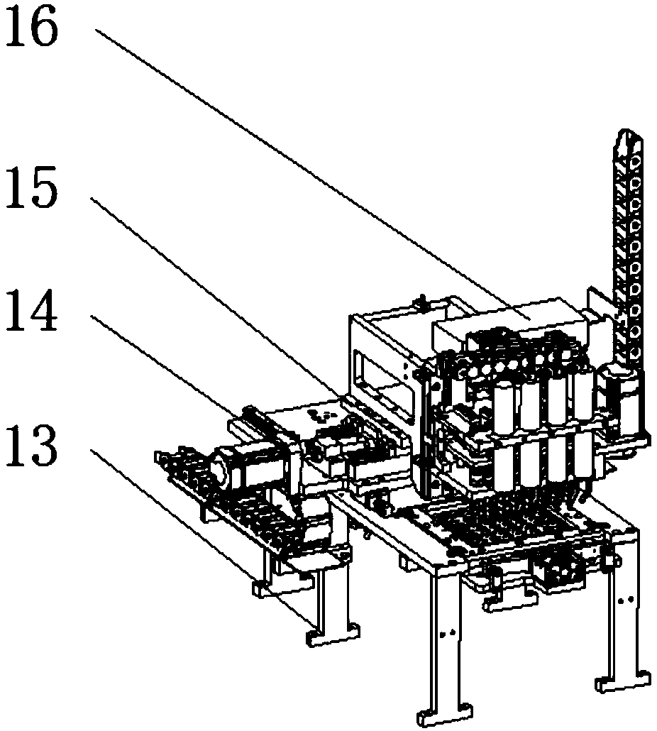
[0017] see Figure 1-5 , an embodiment provided by the present invention: an automatic winding welding equipment, including a winding machine 3, a welding machine 10, an eight-axis synchronous winding and an up and down needle-drawing mechanism 23, one side of the winding machine 3 A wire material discharge rack 4 is installed, and the inside of the winding machine 3 is equipped with a carrier circulating flow device 2, and one end of the top of the winding ma...


PUM


Abstract

The invention discloses an automatic winding welding device comprising a winding machine table, a welding machine table, an eight-axis synchronous winding and an up-and-down needle drawing mechanism.A wire discharging frame is mounted on one side of the winding machine table. An loading water circulation device is mounted in the winding machine table, a winding device is mounted at one end of thetop of the winding machine table through a support, a winding machine head left-right mechanism is mounted on the support on one side of the winding device, the welding machine table is mounted at one end of the winding machine table, and universal wheels are mounted at four corners at the bottom of each of the welding machine table and the winding machine table, a laser welding host is mounted at the top of the welding machine table, and a computer host is mounted at one end of the welding machine table far away from the winding machine table. According to the automatic winding welding device, by installation of a damping gasket, the stability of the whole device is improved, to achieve the effect of vibration reduction, and the influence on work progress and winding welding effects caused by vibration in work is avoided.

Description

technical field [0001] The invention relates to the technical field of mechanical equipment, in particular to an automatic winding welding equipment. Background technique [0002] The inductance coil is a device that uses the principle of electromagnetic induction to work. It is made of wires that are wound around the insulating tube one by one. The wires are insulated from each other, and the insulating tube can be hollow or contain iron cores or magnetic powder cores. At present, most of the induction coil winding and welding equipment is completed by manual hooking using magnetic rings, etc., or the assembled traditional inductor is completed by semi-automatic CNC winding equipment. Complete, these winding devices belong to single-axis winding, which is not only inefficient, but also the bulk form of the output coil is not conducive to the automation of subsequent processes, thus affecting the efficiency of winding, and the welding work cannot be completed automatically. ...

Claims


Application Information

Patent Timeline
Patent Type & Authority Applications(China)
IPC IPC(8): H01F41/06H01F41/09H01F41/076
CPCH01F41/06H01F41/076H01F41/09Y02P70/10
Inventor 张江波
Owner 东莞市高东电子科技有限公司
Why Eureka
Try Eureka