Package stack structure

A packaging stacking and packaging layer technology, applied in the direction of semiconductor/solid-state device components, semiconductor devices, electrical components, etc., can solve the problems of easy delamination, yield reduction, voids, etc., to avoid delamination, increase bonding force, The effect of increasing the contact area

Active Publication Date: 2018-05-25
SILICONWARE PRECISION IND CO LTD
View PDF3 Cites 5 Cited by
  • Summary
  • Abstract
  • Description
  • Claims
  • Application Information

AI Technical Summary

Problems solved by technology

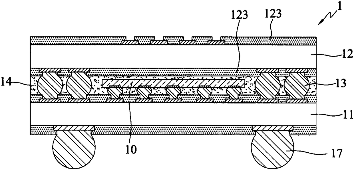
[0004] However, in the existing packaging stack structure 1, the solder resist layer 123 is provided on both sides of the intermediary substrate 12, and the solder resist layer 123 is prone to whitening after multiple processes, so that the packaging compound 14 and the intermediary substrate 12 Easy to delamination (delamination)
[0005] In addition, when forming the encapsulant 14 , air tends to remain between the encapsulation substrate 11 and the interposer substrate 12 , so voids are likely to be generated in the encapsulant 14 , resulting in reduced yield.

Method used


Image

  • Package stack structure
  • Package stack structure
  • Package stack structure

Examples


Embodiment Construction

[0045] Embodiments of the present invention are described below through specific examples, and those skilled in the art can easily understand other advantages and effects of the present invention from the content disclosed in this specification.

[0046] It should be noted that the structures, proportions, sizes, etc. shown in the drawings attached to this specification are only used to match the content disclosed in the specification for the understanding and reading of those skilled in the art, and are not intended to limit the implementation of the present invention. Limiting conditions, so there is no technical substantive meaning, any modification of structure, change of proportional relationship or adjustment of size, without affecting the effect and purpose of the present invention, should still fall within the scope of the present invention. The disclosed technical content must be within the scope covered. At the same time, terms such as "above", "first", "second" and ...


PUM


Abstract

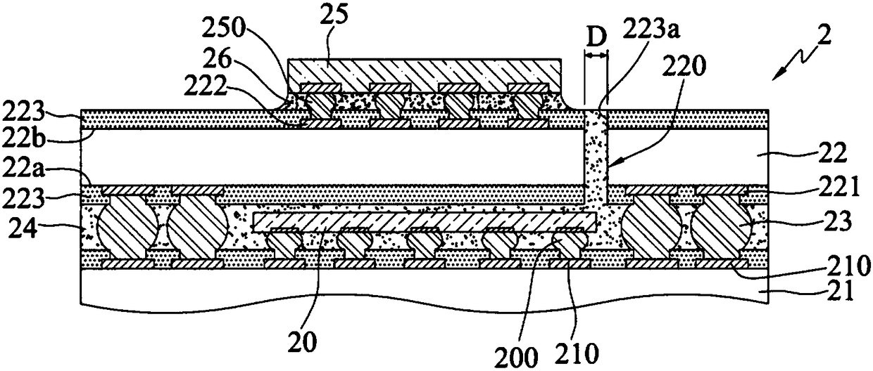
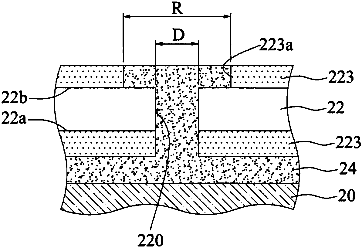
A package stack structure is provided, including a first substrate, a second substrate stacked on the first substrate, and an encapsulant formed between the first substrate and the second substrate. Athrough hole is formed to penetrate the second substrate and allow the encapsulant to be filled therein, thereby increasing the contact area and hence strengthening the bonding between the encapsulant and the second substrate.

Description

technical field [0001] The present invention relates to a package structure, in particular to a package stack structure. Background technique [0002] With the evolution of semiconductor packaging technology, different packaging types have been developed for semiconductor devices. In order to improve electrical functions and save packaging space, stacking multiple packaging structures has been developed to form a package stack structure (Package on Package, referred to as POP) technology, this packaging method can play the heterogeneous integration characteristics of the system package (SiP), and can integrate electronic components with different functions, such as: memory, central processing unit, graphics processor, image application processor, etc. , through stacking design to achieve system integration, suitable for various thin and light electronic products. [0003] figure 1 It is a schematic cross-sectional view of an existing packaging stack structure 1 . Such as ...

Claims


Application Information

Patent Timeline
Patent Type & Authority Applications(China)
IPC IPC(8): H01L23/31H01L23/528H01L23/498H01L23/538
CPCH01L23/3128H01L23/49816H01L23/49838H01L23/5283H01L23/5383H01L23/5385H01L23/3142H01L25/0657H01L25/50H01L2225/06517H01L2225/0652H01L2225/06572H01L24/16H01L2224/16227H01L2224/73204H01L2224/32225H01L24/13H01L24/32H01L24/48H01L2224/48227H01L2224/131H01L2924/014H01L2224/16225H01L2924/00H01L23/3121H01L24/17H01L2224/16113H01L2924/15151H01L2924/2064
Inventor 林长甫姚进财余国华黄富堂
Owner SILICONWARE PRECISION IND CO LTD
Why Eureka
Try Eureka