Low-voltage apparatus convenient to maintain

A technology for low-voltage electrical appliances and housings, which is applied in the field of low-voltage electrical appliances that are easy to maintain, can solve problems such as inconvenient maintenance of low-voltage electrical appliances, and achieve the effects of facilitating the movement of housings, reducing labor intensity, and improving maintenance efficiency.

Inactive Publication Date: 2018-05-25
浙江叶尼塞电气有限公司
4 Cites 3 Cited by

AI-Extracted Technical Summary

Problems solved by technology

[0003] The purpose of the present invention is to provide a low-voltage electrical appliance that is easy to maintain, which has...

Abstract

The invention discloses a low-voltage apparatus convenient to maintain. The low-voltage apparatus convenient to maintain comprises a shell. The bottom of the inner wall of the shell is fixedly connected with an installing base, and the top of the installing base is fixedly connected with a low-voltage apparatus body. Sliding grooves are formed in the left side and the right side of the top of theshell, and the bottoms of the inner walls of the sliding grooves are fixedly connected with first sliding rails. Through the arrangement and cooperation of the first sliding rails, first sliding blocks, top plates, second sliding rails, second sliding blocks, sliding rods, first rotary shafts, limiting grooves, roller bearings, driving wheels, second rotary shafts, driven wheels, drive chains, connecting blocks, connecting rods, rotary discs, handles, limiting ropes, limiting blocks, clamping blocks and clamping grooves, the assembly mode of the sliding rails and the sliding blocks is adopted,maintenance staff can conveniently maintain the low-voltage apparatus, the damaged low-voltage apparatus can be maintained in time, the maintenance efficiency is improved, time and labor are saved, the labor intensity of the maintenance staff is reduced, and great convenience is brought to the maintenance staff.

Application Domain

Technology Topic

Image

  • Low-voltage apparatus convenient to maintain
  • Low-voltage apparatus convenient to maintain
  • Low-voltage apparatus convenient to maintain

Examples

  • Experimental program(1)

Example Embodiment

[0018] The technical solutions in the embodiments of the present invention will be clearly and completely described below in conjunction with the accompanying drawings in the embodiments of the present invention. Obviously, the described embodiments are only a part of the embodiments of the present invention, rather than all the embodiments. Based on the embodiments of the present invention, all other embodiments obtained by those of ordinary skill in the art without creative work shall fall within the protection scope of the present invention.
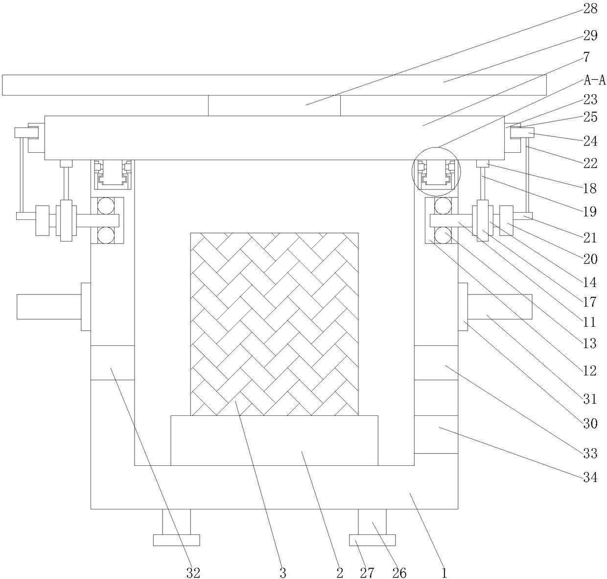
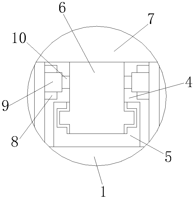
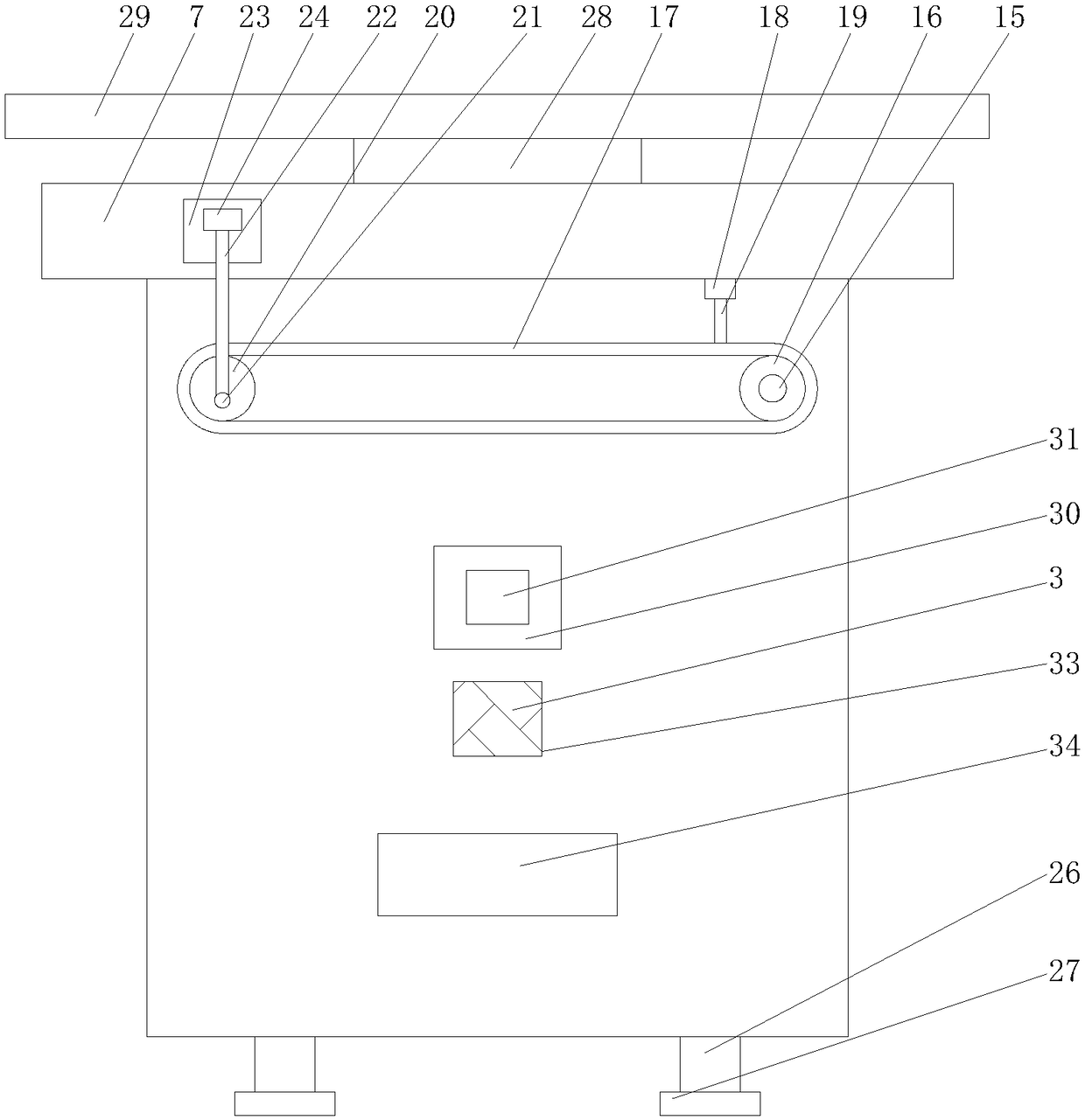
[0019] See Figure 1-4 , A low-voltage electrical appliance that is easy to maintain, includes a housing 1, the bottom of the inner wall of the housing 1 is fixedly connected with a mounting seat 2, the four corners of the bottom of the housing 1 are fixedly connected with legs 26, and the bottom of the legs 26 is fixedly connected with The fixed block 27 serves to fix the housing 1 by setting the fixed block 27 to increase friction and prevent the housing 1 from sliding. The top of the mounting base 2 is fixedly connected to the low-voltage electrical main body 3, and the left and right sides of the top of the housing 1 The sides are provided with sliding grooves 4, the bottom of the inner wall of the sliding groove 4 is fixedly connected with a first slide rail 5, the inner wall of the first slide rail 5 is slidably connected with a first slider 6, and a top plate 7 is provided above the first slider 6, The top of the top plate 7 is fixedly connected with a supporting block 28, and the top of the supporting block 28 is fixedly connected with a dustproof plate 29. The dustproof plate 29 is provided to prevent dust. The tops of the two first sliding blocks 6 pass through the fixed top plate 7. Fixed connection. The left and right sides of the inner wall of the sliding groove 4 are fixedly connected with a second slide rail 8, and the inner wall of the second slide rail 8 is slidably connected with a second sliding block 9, and the left and right sides of the first sliding block 6 pass through sliding rods. 10 is fixedly connected to the second sliding block 9, the left and right sides of the housing 1 and the positions below the sliding groove 4 are provided with first rotating shafts 11, and the left and right sides of the inner wall of the housing 1 are provided at positions corresponding to the first rotating shaft 11 The limiting groove 12 is fixedly connected to the inner wall of the limiting groove 12 with a rolling bearing 13, and one end of the first rotating shaft 11 close to the low-voltage electrical main body 3 successively penetrates the rolling bearing 13 and the limiting groove 12 and extends to the inside of the limiting groove 12 to move with the rolling bearing 13 The surface of the first shaft 11 is fixedly connected to the driving wheel 14. The left and right sides of the housing 1 and the positions below the driving wheel 14 are fixedly connected to the connecting plate 30. The side of the connecting plate 30 away from the housing 1 is fixedly connected There is a handle 31. The connecting plate 30 and the handle 31 are provided to facilitate the movement of the housing 1. The left side of the housing 1 and a position below the handle 31 is provided with a first heat dissipation port 32. A second heat dissipation port 33 is opened on the right side and below the handle 31. The first heat dissipation port 32 and the second heat dissipation port 33 are provided to dissipate heat and prevent the internal temperature of the housing 1 from being too high, resulting in the main body of the low-voltage electrical appliance. 3 When a failure occurs, an observation port 34 is provided on the right side of the housing 1 and below the second heat dissipation opening 33. The observation port 34 is provided to perform an observation function, which is convenient for the staff to observe the low-voltage electrical main body 3. A second rotating shaft 15 is provided on the left and right sides of 1 and at the position behind the first rotating shaft 11. The surface of the second rotating shaft 15 is movably connected with a driven wheel 16, and the driving wheel 14 is drivingly connected to the driven wheel 16 through a transmission chain 17. The left and right sides of the bottom of the top plate 7 are fixedly connected with connecting blocks 18 corresponding to the position of the transmission chain 17. The connecting block 18 is fixedly connected with the transmission chain 17 through the connecting rod 19, and the end of the first rotating shaft 11 away from the driving wheel 14 is fixedly connected with the turntable 20, A handle 21 is fixedly connected to the side of the turntable 20 away from the first rotating shaft 11. The handle 21 makes the first rotating shaft 11 rotate with the rolling bearing 13 inside the limiting groove 12, and the first rotating shaft 11 The driving wheel 14 rotates, the driving wheel 14 drives the driven wheel 16 to rotate through the transmission chain 17, and the transmission chain 17 moves the top plate 7 backward through the connecting block 18 and the connecting rod 19, and the top plate 7 drives the first slider 6 on the first slide rail. The inner sliding of 5 drives the second sliding block 9 to slide inside the second slide rail 8. The top of the handle 21 is fixedly connected to the limit rope 22, the top end of the limit rope 22 is fixedly connected to the limit block 23, and the left and right sides of the top plate 7 The two sides are fixedly connected with a clamping block 24, and the left and right sides of the clamping block 24 are provided with clamping grooves 25 adapted to the position of the limiting block 23. The first sliding rail 5 and the first sliding block 6 are provided. , Top plate 7, second sliding rail 8, second sliding block 9, sliding rod 10, first rotating shaft 11, limiting groove 12, rolling bearing 13, driving wheel 14, second rotating shaft 15, driven wheel 16, transmission chain 17, The connecting block 18, the connecting rod 19, the turntable 20, the handle 21, the limit rope 22, the limit block 23, the clamping block 24 and the clamping groove 25 cooperate with each other. The slide rail and the sliding block are assembled to facilitate maintenance personnel. Maintenance of low-voltage electrical appliances can repair damaged low-voltage electrical appliances in a timely manner, which improves maintenance efficiency, not only saves time and effort, but also reduces the labor intensity of maintenance personnel and brings great convenience to maintenance personnel.
[0020] When in use, the clamping block 24 is taken out of the clamping groove 25 through the limit rope 22, and then the first rotating shaft 11 rotates with the rolling bearing 13 inside the limit groove 12 through the handle 21, and the first rotating shaft 11 drives the drive The wheel 14 rotates, the driving wheel 14 drives the driven wheel 16 to rotate through the transmission chain 17, the transmission chain 17 makes the top plate 7 move backward through the connecting block 18 and the connecting rod 19, and the top plate 7 drives the first slider 6 on the first slide rail 5. Internal sliding drives the second sliding block 9 to slide inside the second sliding rail 8 to open the housing 1 so that maintenance personnel can maintain the main body 3 of the low-voltage electrical appliance.
[0021] To sum up: the low-voltage electrical appliance that is easy to maintain is provided with a first slide rail 5, a first slide block 6, a top plate 7, a second slide rail 8, a second slide block 9, a slide rod 10, a first rotating shaft 11, Limit groove 12, rolling bearing 13, driving wheel 14, second rotating shaft 15, driven wheel 16, transmission chain 17, connecting block 18, connecting rod 19, turntable 20, handle 21, limit rope 22, limit block 23, card The connecting block 24 and the clamping groove 25 cooperate with each other to solve the problem of inconvenient maintenance of common low-voltage electrical appliances.
[0022] Although the embodiments of the present invention have been shown and described, those of ordinary skill in the art can understand that various changes, modifications, and substitutions can be made to these embodiments without departing from the principle and spirit of the present invention. And variations, the scope of the present invention is defined by the appended claims and their equivalents.

PUM

no PUM

Description & Claims & Application Information

We can also present the details of the Description, Claims and Application information to help users get a comprehensive understanding of the technical details of the patent, such as background art, summary of invention, brief description of drawings, description of embodiments, and other original content. On the other hand, users can also determine the specific scope of protection of the technology through the list of claims; as well as understand the changes in the life cycle of the technology with the presentation of the patent timeline. Login to view more.

Similar technology patents

Classification and recommendation of technical efficacy words

  • Reduce labor intensity
  • Improve maintenance efficiency

City regional railway signal system and control method thereof

ActiveCN103754242ARun fastReduce labor intensityAutomatic systemsRailway signalEngineering
Owner:CHINA RAILWAY SIYUAN SURVEY & DESIGN GRP

Monitoring method and terminal device of track circuit device

ActiveCN108501980AGuaranteed operational safetyImprove maintenance efficiencyVehicle route interaction devicesCase baseTerminal equipment
Owner:固安信通信号技术股份有限公司
Why Eureka
Try Eureka