Portable BTM detector

A detector and portable technology, applied in the field of railway signal equipment detection, can solve the problems of danger of strong electricity, damaged equipment, cable connection errors, etc., and achieve the effect of convenient on-site application

Active Publication Date: 2018-05-25
BEIJING JIAODA SIGNAL TECH
View PDF4 Cites 5 Cited by
  • Summary
  • Abstract
  • Description
  • Claims
  • Application Information

AI Technical Summary

Problems solved by technology

At present, the detection of BTM installed on site is mainly through visual inspection, or the operator uses the transponder to send a message under the BTM antenna and observes the status of the BTM indicator light to check whether the transponder excitation signal can successfully activate the transponder. It is not possible to quantitatively evaluate the emission performance of the BTM antenna, and it is not portable
[0003] The following problems exist in the current BTM detection device: 1. Need to receive the message data from the interface (hereinafter referred to as the B interface) of the BTM host and the vehicle-mounted equipment. To the B interface, the ground equipment that sends the data is analyzed. After the detection is completed, it is necessary to reconnect the BTM equipment to the vehicle equipment cable
There are great installation risks in such an operation, including incorrect cable connection, looseness, damage to equipment, etc.; 2. All equipment is integrated in the inspection vehicle, and the operator needs to go down to the maintenance ditch when performing on-site inspection. For the operator There will be problems of electromagnetic radiation, and there will be dangers of strong electricity; 3. The equipment networking cannot be realized, that is, the test results cannot be automatically backed up to the server or the Internet, which is not convenient for data storage and subsequent analysis; 4. The test system is relatively large, Does not have good portability; 5. Some measuring devices determine the center point of the BTM antenna by artificially shrinking the fixing device, and the transmitting antenna cannot be completely positioned at the geometric center point of the BTM antenna through manual positioning

Method used


Image

  • Portable BTM detector
  • Portable BTM detector
  • Portable BTM detector

Examples


Embodiment 1

[0030] Embodiment 1 The configuration scheme for detecting the excitation signal of the transponder and the distance from the antenna to the rail plane

[0031] The main function of the vehicle-mounted BTM equipment is to generate the radio frequency energy signal to activate the transponder, and to receive and process the uplink signal from the transponder. The BTM antenna unit should provide energy for the transponder by generating a magnetic field. If the radio frequency energy signal of the BTM antenna is emitted If it is too low, the transponder may not be detected by the on-board equipment, causing loss of spots. If the radio frequency energy signal emission level is too high, it may cause crosstalk. According to the subset036 specification, the field strength generated by the BTM antenna is on the transponder at any position relative to the antenna The magnetic flux of the reference area is defined. The detector is calibrated in a standard laboratory environment with a sta...

Embodiment 2

[0038] Embodiment 2 The method for detecting the excitation signal of the transponder transmitted by the BTM antenna implemented in this application has the following steps:

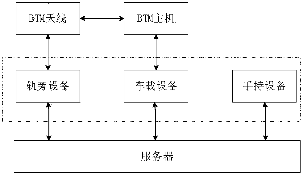
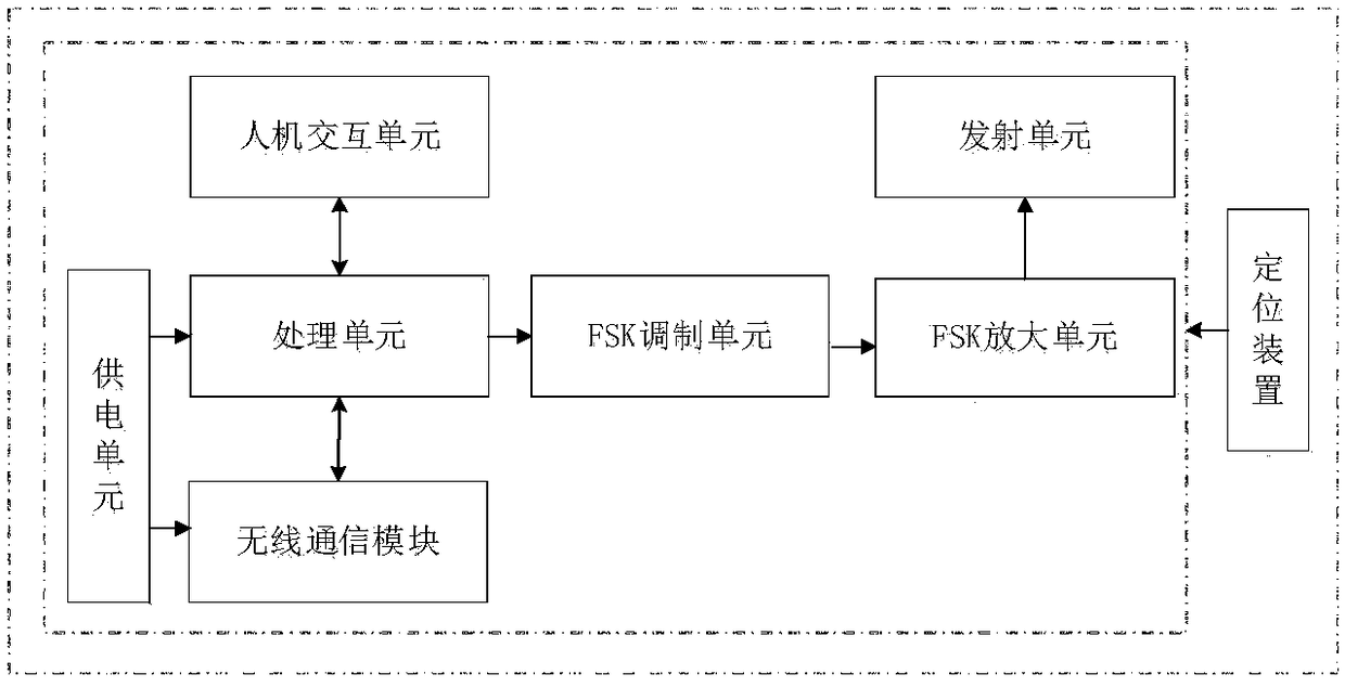
[0039] 1) Power on the trackside equipment through the power button, and then perform power-on self-checking on the trackside equipment; place the trackside equipment in the middle of the two steel rails below the antenna, and use the laser pointer to locate the trackside equipment receiving unit. Position it directly below the geometric center of the BTM antenna;

[0040] 2) Configure the server / handheld device to establish a wireless connection with the trackside device;

[0041] 3) Perform the test by operating the human-computer interaction of the trackside equipment or the handheld device, and set the tester information, the tested BTM equipment information, the tested locomotive information, etc.; after the receiving unit receives the transponder excitation signal, it is rectified and filtered and transmi...

Embodiment 3

[0052] Embodiment 3 The method for closed-loop detection of BTM receiving and sending messages implemented in this application has the following steps:

[0053] 1) Power on the trackside equipment through the power button, and the equipment will perform power-on self-check after power-on; place the trackside equipment in the middle of the rail, and use the laser pointer to locate the trackside equipment transmitting antenna and position it to the BTM antenna geometry Right below the center.

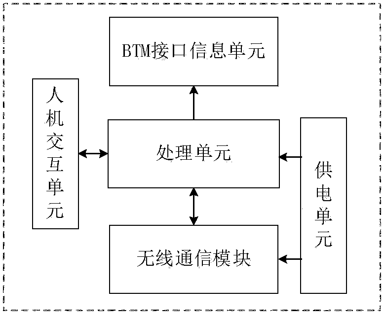
[0054] 2) Connect the vehicle-mounted equipment to the B interface of the BTM host through a cable, or connect the vehicle-mounted equipment to the T interface of the BTM host, and the vehicle-mounted equipment is powered on and self-checking.

[0055] 3) After the server establishes wireless communication with on-board equipment and trackside equipment, test selection is performed, and tester information, tested BTM equipment information, tested locomotive information, etc. are set; after setti...


PUM


Abstract

The invention relates to a portable BTM detector. The portable BTM detector comprises onboard equipment, trackside equipment and hand-held equipment, wherein the onboard equipment is electrically connected with a BTM host, extracts and sends a desired packet and BTM state information to a server, the trackside equipment receives and measures radio frequency energy sent by a BTM antenna and measures a distance between a BTM antenna and a steel rail surface, and simulates and sends a packet signal of an FSK transponder, the hand-held equipment is used for generating a report and displaying a test result, and the onboard equipment, the trackside equipment and the hand-held equipment are all in wireless communication with the server and are all installed in a portable case. The detector that can be put in the portable case can detect an excitation signal of the transponder, measure a distance between the BTM antenna and the rail surface, and detect a packet receiving and sending function in a closed cycle, realizes networking, uploads a test result to a server automatically, and adapts to various existing BTM host interfaces due to configuration of a BTM information interaction unit, thereby being very conveniently used in site.

Description

Technical field [0001] The invention relates to the detection application field of railway signal equipment, in particular to a portable BTM detector and a detection method. technical background [0002] The transponder message transmission module (BTM) is mainly composed of the BTM host and the BTM antenna. The main function is to transmit the activation energy signal to the ground transponder through the transmitting antenna, and to receive the uplink message sent by the transponder through the receiving antenna Data, the message data is sent to the on-board train control equipment, so the identification and diagnosis, regular maintenance and detection of the abnormality of the BTM host and antenna are particularly important. At present, the detection of BTM that has been installed on site is mainly through visual inspection, or the operator uses a transponder to send a message under the BTM antenna and then observes the status of the BTM indicator to verify whether the transpo...

Claims


Application Information

Patent Timeline
Patent Type & Authority Applications(China)
IPC IPC(8): H04B17/14H04B17/15H04B17/29
CPCH04B17/14H04B17/15H04B17/29
Inventor 王永和刘洋刘星宇
Owner BEIJING JIAODA SIGNAL TECH
Why Eureka
Try Eureka