Snow removal anti-skid damping shoe
A shock-absorbing shoe and anti-skid technology, applied in footwear, soles, clothing and other directions, can solve the problem of inability to effectively remove snow on the soles, and achieve good anti-skid effect and shock absorption effect, simple operation, and ingenious structure.
- Summary
- Abstract
- Description
- Claims
- Application Information
AI Technical Summary
Problems solved by technology
Method used
Image

Examples
Embodiment Construction
[0011] The specific implementation manners of the present invention will be described in further detail below in conjunction with the accompanying drawings.
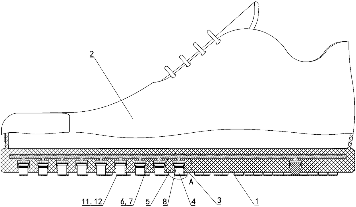
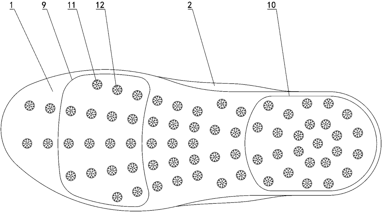
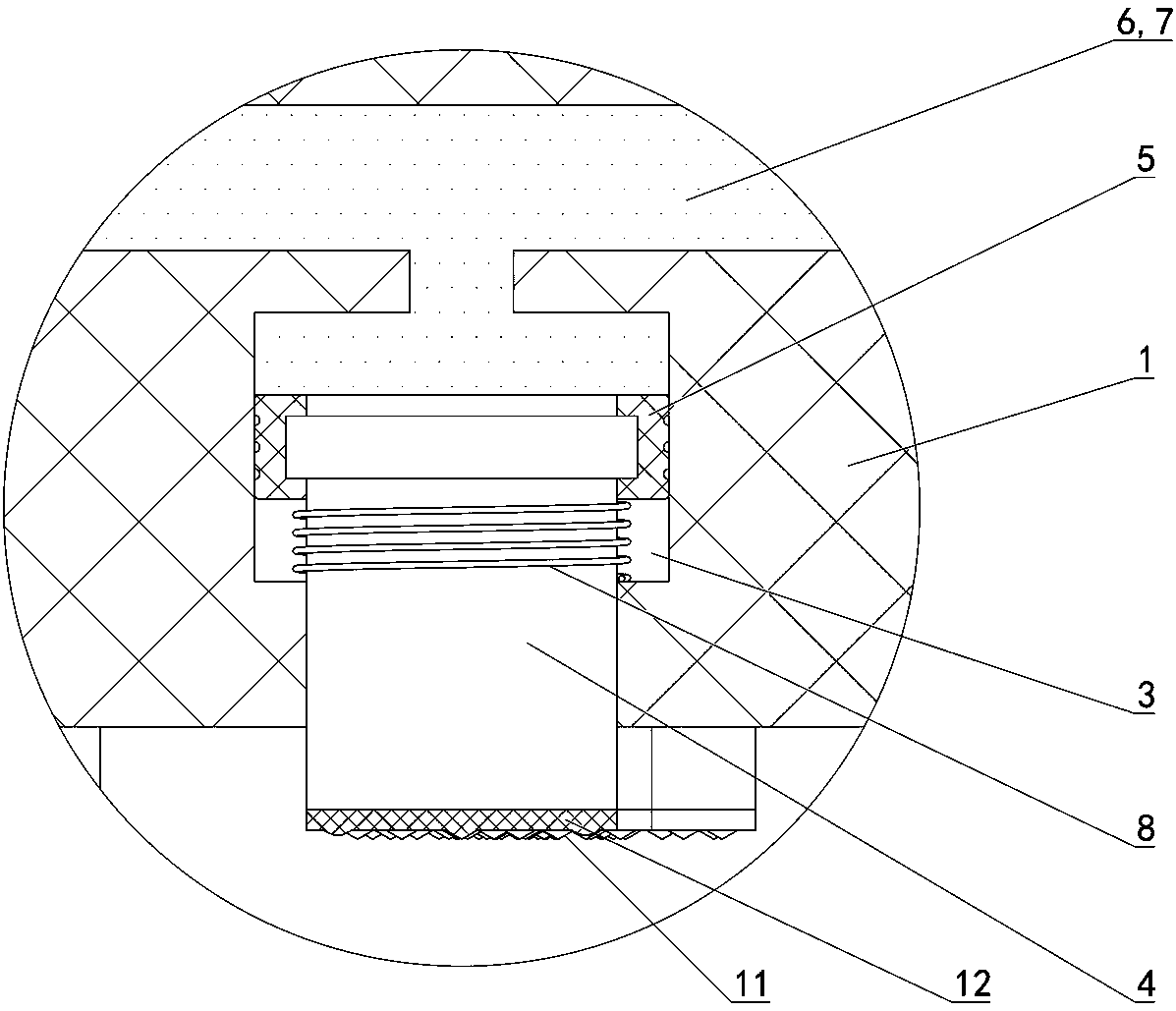
[0012] Depend on Figure 1 to Figure 4 Provided, the present invention includes a horizontally arranged sole 1 and a shoe upper 2 placed above the sole 1, a plurality of vertical chute 3 distributed horizontally on the sole 1 and vertically slidable sliding grooves corresponding to the vertical chute 3 one-to-one. slider 4, the upper end of the slider 4 is placed in the chute 3, the lower end of the slider 4 can slide out of the sole 1 and placed outside the sole 1, the upper end of the slider 4 is equipped with a slider that can slide in the chute 3 Piston head 5; the inside of the sole 1 has a cavity 6 placed above the plurality of chutes 3, the cavity 6 communicates with the plurality of chutes 3, and the cavity 6 communicates with the cavity 6 of the chute 3 The part is filled with fluid medium 7.
[0013] As a pre...
PUM
 Abstract
Description
Claims
Application Information
 - Generate Ideas
- Intellectual Property
- Life Sciences
- Materials
- Tech Scout
- Unparalleled Data Quality
- Higher Quality Content
- 60% Fewer Hallucinations
Browse by: Latest US Patents, China's latest patents, Technical Efficacy Thesaurus, Application Domain, Technology Topic, Popular Technical Reports.
© 2025 PatSnap. All rights reserved.Legal|Privacy policy|Modern Slavery Act Transparency Statement|Sitemap|About US| Contact US: help@patsnap.com