Air inlet and outlet structure of food processor

A food cooking machine, the technology of air in and out, applied in the direction of home appliances, applications, kitchen utensils, etc., can solve the problems of unstable placement of the machine, affecting the appearance of the machine, poor heat dissipation effect, etc., to improve the heat dissipation effect, the product appearance is beautiful, reduce area effect

Pending Publication Date: 2018-05-29
FOSHAN VIOMI ELECTRICAL TECH +1
View PDF5 Cites 3 Cited by
  • Summary
  • Abstract
  • Description
  • Claims
  • Application Information

AI Technical Summary

Problems solved by technology

During the process of mixing food, the rotation of the motor will generate heat. If it is not removed in time, it will cause the motor to overheat and cause the motor to burn out, etc.
At present, there are two types of air inlet and outlet for the wall breaking machine: one is: the air enters from both sides of the machine, and the air exits from the base; among them, the side air inlet is located on the main machine shell, which is obviously exposed and affects the appearance of the machine, while the air outlet is located on the bottom of the base, so the base It is necessary to raise the feet to ensure that the air outlet is away from the table. The area of ​​the feet is very small, so that the machine is not stable
The other is: the air inlet and outlet are on the bottom of the base, and the heat-exchanged air from the air outlet is easily sucked by the air inlet. After continuous circulation, the air flowing through the surface of the motor is hot air, so the heat dissipation effect is poor.

Method used


Image

  • Air inlet and outlet structure of food processor
  • Air inlet and outlet structure of food processor
  • Air inlet and outlet structure of food processor

Examples


Embodiment Construction

[0031] The present invention will be further described below in conjunction with accompanying drawing and embodiment:

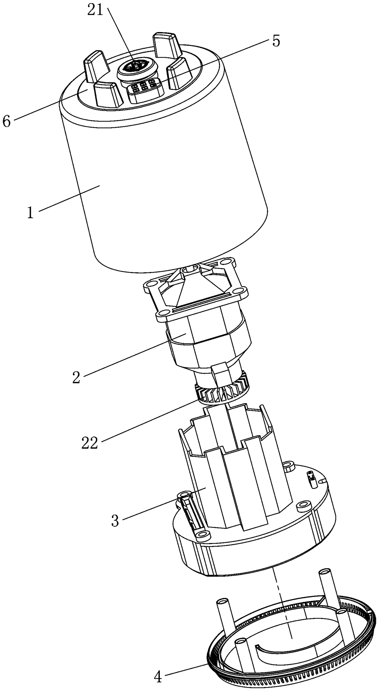
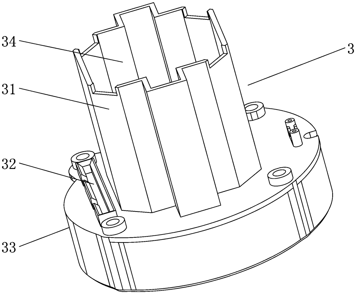
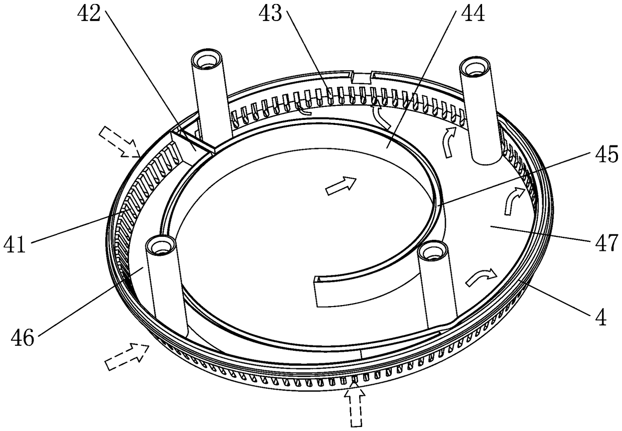
[0032] see Figure 1 to Figure 7 As shown, a food cooking machine air inlet and outlet structure includes a main engine assembly, the main engine assembly includes a shell assembly and a motor 2, the outer top of the shell assembly is provided with a first transmission joint 21, the motor 2 is arranged in the shell assembly, and is connected to the second A transmission joint 21 is transmission connected, and the motor 2 is also transmission connected with a fan 22. The housing assembly is provided with an air duct, the motor 2 and the fan 22 are arranged in the air duct, and the air duct is provided with a mutually connected air inlet cavity 11 and an air outlet Cavity 35; the outer periphery of the lower part of the shell assembly is provided with an air inlet 41 and an air outlet 43, the air inlet 41 communicates with the air inlet chamber 11, and the air ...


PUM


Abstract

The invention relates to an air inlet and outlet structure of a food processor. The air inlet and outlet structure of the food processor comprises a main machine assembly. The main machine assembly comprises a housing component and a motor. The outer top of the housing component is provided with a first transmission connector. The motor is installed in the housing component, and is in the transmission connection with the first transmission connector. The motor is further in the transmission connection with a fan. The housing component is internally provided with an air channel. The motor and the fan are installed in the air channel. The air channel is provided with an air inlet cavity and an air outlet cavity which are mutually communicated. The periphery of the lower part of the housing component is provided with an air inlet and an air outlet. The air inlet is communicated with the air inlet cavity, and the air outlet is communicated with the air outlet cavity. The air inlet and theair outlet of the air inlet and outlet structure of the food processor are installed at the periphery of the lower end of the housing component, so the air exhausting speed is increased, the area of an airflow channel is reduced, the air flow of the whole machine is reinforced, and the heat dissipation effect is improved. The noise of the motor is greatly reduced because the air exhausting speed is rapid.

Description

technical field [0001] The invention relates to a heat dissipation structure of a motor of a food cooking machine, in particular to an air inlet and outlet structure of a food cooking machine. Background technique [0002] In current wall breaking machines, the motor in the main machine is generally used to provide crushing power in the mixing cup. During the process of food mixing, the rotation of the motor will generate heat. If it is not removed in time, it will cause the motor to overheat and cause the motor to burn out. At present, there are two types of air inlet and outlet for the wall breaking machine: one is: the air enters from both sides of the machine, and the air exits from the base; among them, the side air inlet is located on the main machine shell, which is obviously exposed and affects the appearance of the machine, while the air outlet is located on the bottom of the base, so the base It is necessary to raise the feet to ensure that the air outlet is away ...

Claims


Application Information

Patent Timeline
IPC IPC(8): A47J43/07
CPCA47J43/0716
Inventor 陈小平
Owner FOSHAN VIOMI ELECTRICAL TECH
Why Eureka
Try Eureka