Shutter type vertical drying machine and material drying system adopting drying machine

A vertical dryer and drying system technology, applied in the direction of drying solid materials, drying, lighting and heating equipment, etc., can solve the problems of reducing material passages, failing to improve drying efficiency, and failing to meet the requirements at one time. To achieve the effect of increasing the exhaust velocity

Inactive Publication Date: 2013-12-18
ZHEJIANG DEYAO ENERGY SAVING TECH CO LTD
View PDF8 Cites 1 Cited by
  • Summary
  • Abstract
  • Description
  • Claims
  • Application Information

AI Technical Summary

Problems solved by technology

[0005] For the former, in order to increase the output, the radius of the cylinder can only be increased. Although this method can increase the output to a certain extent, if the design of the retaining ring is too small, most of the dried materials cannot be reached at one time. If the design of the retaining ring is too large, the material channel will be reduced accordingly, not only can not improve the drying efficiency, but also cause waste of heat energy. In view of this problem, the Chinese patent with the notification number CN102003869A discloses a Vertical double-cylinder dryer, the vertical double-cylinder dryer adopts the method of setting an inner cylinder in the cylinder, and then setting a retaining ring and a lifting plate between the two cylinders to solve the above problems. good solution
[0006] For the latter, if you want to improve the heat exchange efficiency between hot air and materials, you need to increase the amount of hot air. At present, there is no way to increase the amount of hot air of the vertical dryer and how to increase the amount of material and material in the prior art. Information on hot air exposure time

Method used


Image

  • Shutter type vertical drying machine and material drying system adopting drying machine
  • Shutter type vertical drying machine and material drying system adopting drying machine
  • Shutter type vertical drying machine and material drying system adopting drying machine

Examples


Embodiment Construction

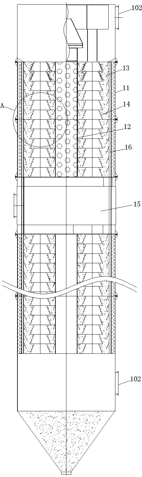
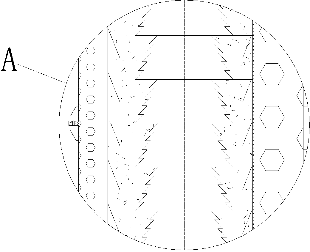
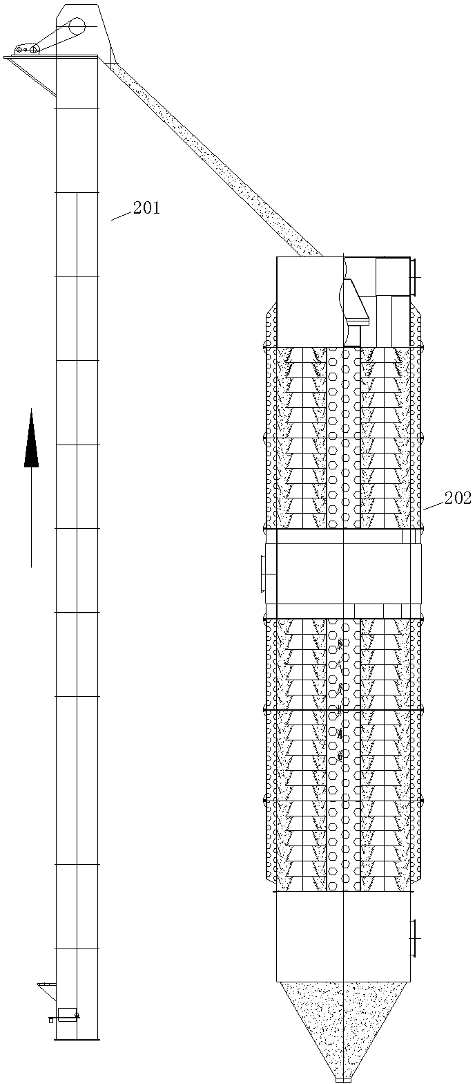
[0024] Examples of louver-type vertical dryers, such as Figure 1-2 As shown, the vertical dryer is a double-cylinder vertical dryer, which includes an outer cylinder 11, an inner cylinder 12, and a lifting plate 13 and a retaining ring 14 arranged between the inner and outer cylinders. Wherein the outer cylinder body 11 is a jacketed structure, and a waste gas channel 101 is arranged in the cylinder wall. In this embodiment, the dryer includes two drying sections, an upper and a lower one, and a waste gas discharge pipe 15 arranged between the two drying sections. In addition, each drying section is provided with a hot air inlet 102; the material retaining ring 14 is composed of a plurality of annular material retaining blades, in this embodiment, each material retaining ring 14 has five material retaining blades, which are connected by Ribs (not shown in the figure) are fixedly connected together and form a louver structure. Fixing the corresponding retaining blades through ...


PUM


Abstract

The invention relates to the field of material drying equipment, and in particular to a shutter type vertical drying machine and a material drying system adopting the drying machine. The shutter type vertical drying machine comprises a tube body and material blocking rings arranged in the tube body, wherein each material blocking ring consists of more than two annular material blocking blades, and the material blocking blades of the same material blocking ring are fixed together and form a shutter structure. Because each material blocking ring of the shutter type vertical drying machine consists of the more than two annular material blocking blades, the material blocking blades of the same material blocking ring are fixed and form the shutter structure. The area of an air outlet of a hot air passage formed by each material blocking ring is increased through the shutter type material blocking ring, in the use process, on one hand, the hot air quantity introduced into the tube body can be increased, on the other hand, the contact area between materials and hot air can be increased, and the heat exchange efficiency between the materials and the hot air is improved. Therefore, the shutter type vertical drying machine has the advantage that the drying efficiency of the vertical drying machine is improved in a way of increasing the hot air quantity of the vertical drying machine.

Description

technical field [0001] The invention relates to the field of material drying equipment, in particular to a louver-type vertical dryer and a material drying system using the dryer. Background technique [0002] Vertical dryer is a very common material drying equipment. At present, it is widely used in building materials, metallurgy, chemical industry and other fields. [0003] In recent years, through continuous development and improvement, there are various vertical dryers available on the market, among which the vertical dryer disclosed in the Chinese patent application with publication number CN1673661A is exactly one of many vertical dryers. kind. The vertical dryer includes a cylinder body and a material retaining ring and a lifting plate arranged in the cylinder body. The material retaining ring is a tapered sleeve that gradually becomes larger from top to bottom, which is located at the center of the cylinder body and is connected with the cylinder body The coaxial l...

Claims


Application Information

Patent Timeline
Patent Type & Authority Applications(China)
IPC IPC(8): F26B25/04F26B25/00
Inventor 唐德顺李霖
Owner ZHEJIANG DEYAO ENERGY SAVING TECH CO LTD
Why Eureka
Try Eureka