
Compressive sealing device

A sealing device and sealing gas technology, which is applied to the sealing device of the engine, engine components, machines/engines, etc., can solve the problems of large contact area between the piston and the cylinder, high manufacturing cost, and large frictional resistance

Inactive Publication Date: 2020-10-20
袁新文
View PDF0 Cites 0 Cited by
  • Summary
  • Abstract
  • Description
  • Claims
  • Application Information

AI Technical Summary

Problems solved by technology

The disadvantage is that the contact area between the piston and the cylinder is large, resulting in large frictional resistance; when the piston stroke is long, the lubrication condition at the top of the cylinder becomes poor, and the cylinder and piston will cause poor sealing after reciprocating wear; in addition, the piston ring and the piston ring groove The matching accuracy requirements are high, the processing is difficult, and the manufacturing cost is high

Method used


Image

  • Compressive sealing device
  • Compressive sealing device
  • Compressive sealing device

Examples


Embodiment 1

[0048] It is applied to the embodiment of the double-cavity intake and exhaust device.

[0049] The combined use of the two sealing inserts can realize the independent completion of air intake by setting the air intake device on the piston, and complete the exhaust from the cylinder head alone, which speeds up the air intake and exhaust speed and makes the direction of the air flow consistent, making the air flow more efficient. smooth.

[0050] Such as Figure 8 , Figure 9 , Figure 12 Shown: the double-chamber intake and exhaust device consists of cylinder head 15, cylinder block A16, cylinder block B17, cylinder block C18, piston 22 with air passage, upper seal insert 30, lower seal insert 31, intake valve 21, Valve pull rod 24, valve spring 25, valve strut 26 and other components are combined,

[0051] The intake stroke and the exhaust stroke of the dual-chamber intake and exhaust device are independently completed by the piston 22 with air passage and the cylinder he...


PUM

PropertyMeasurementUnit
Thicknessaaaaaaaaaa
Thicknessaaaaaaaaaa
The inside diameter ofaaaaaaaaaa

Abstract

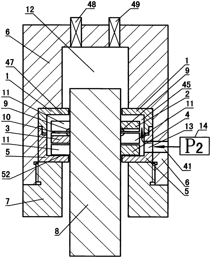
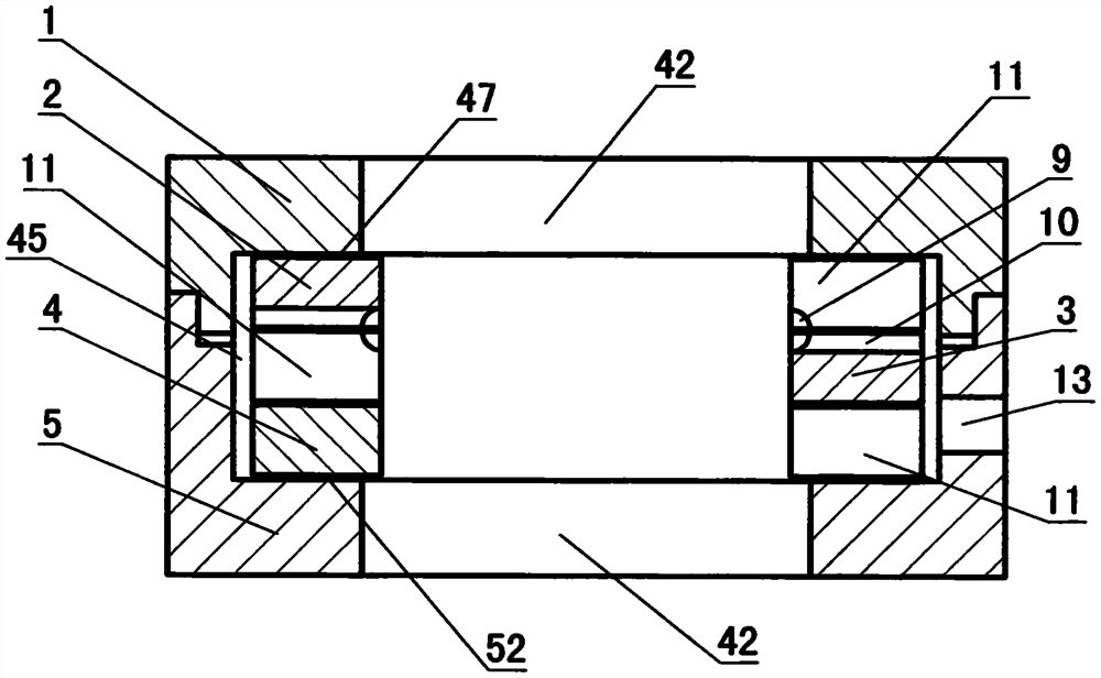
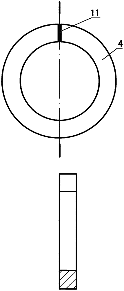
The invention discloses a compressive sealing device for piston and cylinder sealing. The compressive sealing device is formed by combination of inner bushings, outer bushings, a sealing gas ring anda sealing oil ring; the inner bushings and the outer bushings are embedded each other to form sealing bushings; each sealing bushing is a cylinder with holes in the middle; the sealing gas ring and the sealing oil ring are installed in a cavity of the cylinder; by means of an inward compressive force, inner diameters of the sealing rings are tightly attached to the outer diameter of a piston to achieve sealing; two sides of the cylinder are each provided with a piston sliding sleeve; when the piston does reciprocating motion, the outer diameter of the piston only slides in inner diameters of the piston sliding sleeves; with the coordinated use of the two sealing bushings, a gas inlet unit can be arranged on the piston to complete gas intake alone, and exhaust is completed separately from acylinder head, and thus, the gas intake velocity and the exhaust velocity are accelerated and directions of gas flowing are consistent, and the gas flowing is more smooth.

Description

technical field [0001] The invention relates to a sealing device, in particular to a compression sealing device. Background technique [0002] In the reciprocating crank-connecting rod internal combustion engine, an expansion piston ring is installed on the piston for sealing between the cylinder and the piston. This sealing device is widely used at present because of its better sealing effect. [0003] The advantages of this sealing device are good sealing performance and reliable operation. The disadvantage is that the contact area between the piston and the cylinder is large, resulting in large frictional resistance; when the piston stroke is long, the lubrication condition at the top of the cylinder becomes poor, and the cylinder and piston will cause poor sealing after reciprocating wear; in addition, the piston ring and the piston ring groove The requirements for matching accuracy are high, the processing is difficult, and the manufacturing cost is high. Contents of...

Claims


Application Information

Patent Timeline
IPC IPC(8): F02F11/00F02F3/00F01M9/00F02D13/02
CPCF01M9/00F02D13/02F02F3/00F02F11/00F02F2003/0007
Inventor 袁新文
Owner 袁新文
Learn More