Fuel engine

A fuel engine and engine technology, which is applied to combustion engines, internal combustion piston engines, engine components, etc., can solve the problems of unfavorable energy conservation, environmental protection and resource utilization, inability to reduce harmful substances in exhaust gas, and high maintenance costs. The effect of fast power and exhaust gas circulation

Inactive Publication Date: 2018-05-04
林晓丽
View PDF0 Cites 1 Cited by
  • Summary
  • Abstract
  • Description
  • Claims
  • Application Information

AI Technical Summary

Problems solved by technology

[0003] In the exhaust gas of the engine, for every 15 kg of air on average, 1 kg of gasoline is consumed, and about 200 grams of carbon monoxide, about 8 grams of hydrocarbons and other harmful exhaust gases are emitted. Due to the dust accumulation in the engine, it is impossible to restore the harmful substances in the exhaust gas. This shortcoming is a common problem in existing fuel engines.
[0004] The structure of the turbocharger device of the existing automobile is complicated, and the structure of the intake impeller and the exhaust impeller is respectively driven by two worm gears, which has defects such as high manufacturing cost, high manufacturing precision, high maintenance cost, and high probability of damage
[0005] There is a large amount of heat energy in the exhaust gas, and direct emission is harmful to the atmosphere, and it is not conducive to energy conservation, environmental protection and resource utilization

Method used


Image

  • Fuel engine
  • Fuel engine
  • Fuel engine

Examples


Embodiment Construction

[0047] The following are specific embodiments of the present invention and in conjunction with the accompanying drawings, the technical solutions of the present invention are further described, but the present invention is not limited to these embodiments.

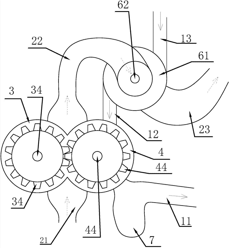
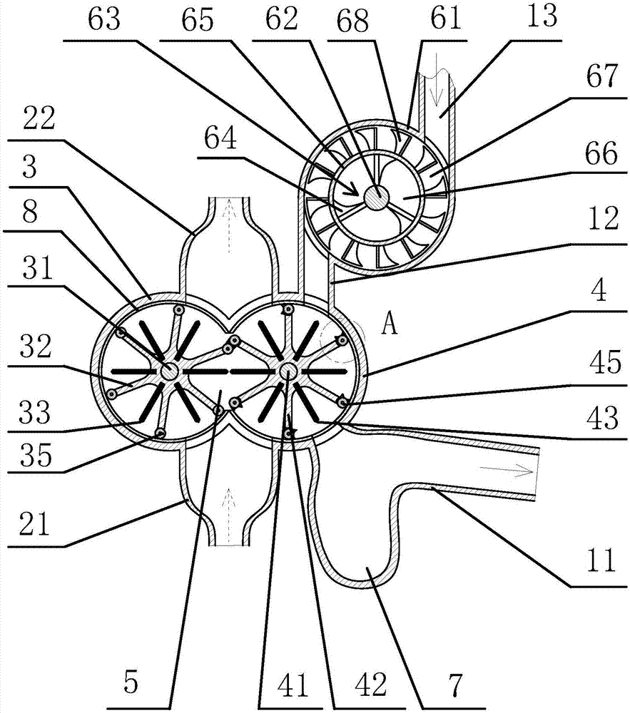
[0048] Such as figure 1 and figure 2 As shown, the engine includes a main intake pipe 11 and a main exhaust pipe 21, and the intake and exhaust system includes a circular first cylinder block 3 and a circular second cylinder block 4, and the first cylinder block 3 and the second cylinder block There is a fan-shaped notch on the side wall of 4, and the notch edge of the first cylinder body 3 is connected with the notch edge of the second cylinder body 4, so that the inner cavity of the first cylinder body 3 communicates with the inner cavity of the second cylinder body 4 The first rotating shaft 31 is connected to the rotation in the first cylinder body 3, and the second rotating shaft 41 is connected to the rotation in t...


PUM


Abstract

The invention provides a fuel engine and belongs to the technical field of engines. The fuel engine comprises a round first cylinder body and a round second cylinder body; two adjacent first blockingplates and two corresponding adjacent second blocking plates form a sealed waste gas combustion chamber between a first rotary shaft and a second rotary shaft; a main exhaust pipe is connected with the perimeter walls of one sides of the first cylinder body and the second cylinder body and the air outlet direction of the main exhaust pipe is located between the first rotary shaft and the second rotary shaft; a middle exhaust pipe is connected with the perimeter walls of the other sides of the first cylinder body and the second cylinder body and the air outlet direction of the main exhaust pipeis right opposite to the air inlet direction of the middle exhaust pipe; the middle exhaust pipe is connected with a tail exhaust pipe; a first high-pressure electrode is arranged between each two adjacent first blocking plates and a second high-pressure electrode is arranged between each two adjacent second blocking plates; each first high-pressure electrode and the corresponding second high-pressure electrode can form breakdown electric sparks during the rotation of the first rotary shaft and the second rotary shaft. The fuel engine has the advantages of being compact in structure and the like.

Description

technical field [0001] The invention belongs to the technical field of engines and relates to a fuel engine. Background technique [0002] Engine intake and exhaust system includes intake system, exhaust system, turbo system, exhaust gas recirculation system, etc. [0003] In the engine exhaust gas, for every 15 kg of air on average, 1 kg of gasoline is consumed, and about 200 g of carbon monoxide, about 8 g of hydrocarbons and other harmful exhaust gases are emitted. Due to dust accumulation in the device, etc., the harmful substances in the exhaust gas cannot be well reduced. This drawback is a common problem in existing fuel engines. [0004] The structure of the existing vortex supercharging device of the automobile is complex, and the intake impeller and the exhaust impeller are respectively driven by two worm gears, which has defects such as high manufacturing cost, high manufacturing precision, high maintenance cost, and high probability of damage. [0005] There is...

Claims


Application Information

Patent Timeline
Patent Type & Authority Applications(China)
IPC IPC(8): F02M35/104F01N13/08F01N3/08F01N5/02F02M31/08F02B37/00F02B27/00
CPCF01N3/08F01N5/02F01N13/08F01N13/082F01N2570/10F02B27/00F02B37/00F02M31/042F02M31/08F02M35/104Y02T10/12
Inventor 林晓丽范存璐
Owner 林晓丽
Why Eureka
Try Eureka