Test-tube stand for medical examination

A test tube rack and medical technology, applied in the field of medical equipment, can solve the problems of inconvenient use of test tube racks, slippage of test tubes, single function of test tube racks, etc., and achieve the effect of facilitating work and improving accuracy

Inactive Publication Date: 2018-05-29
李文文
View PDF0 Cites 2 Cited by
  • Summary
  • Abstract
  • Description
  • Claims
  • Application Information

AI Technical Summary

Problems solved by technology

[0004] The technical problem to be solved by the present invention is: in order to solve the problems existing in the above-mentioned background technology, a test tube rack for medical examination is provided, which solves the problem that the test tube rack is inconvenient to use and easily causes the test tube to slip and the test tube rack has a single function and does not have the function of heating and heat preservation. question

Method used


Image

  • Test-tube stand for medical examination
  • Test-tube stand for medical examination

Examples


Embodiment 1

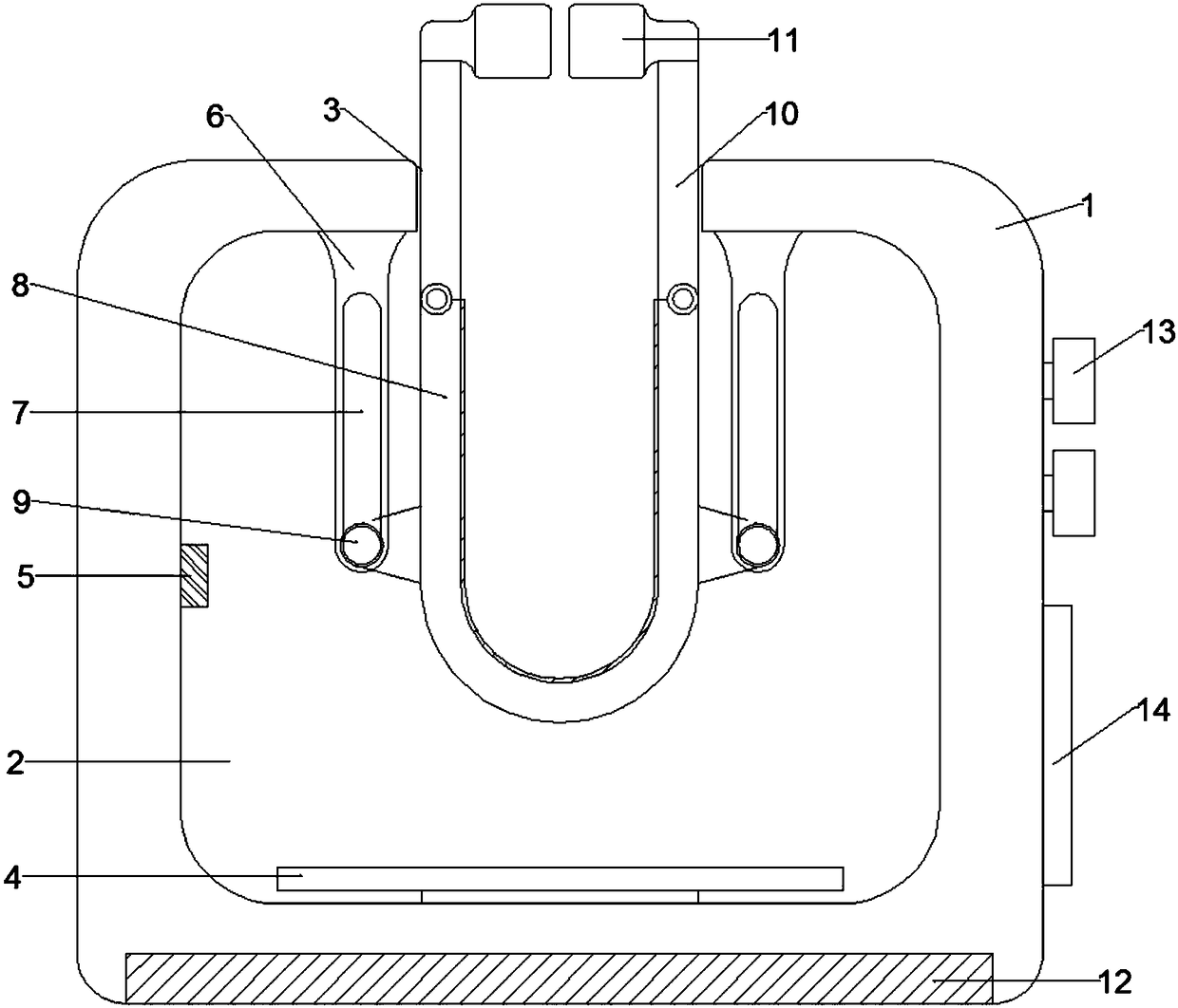
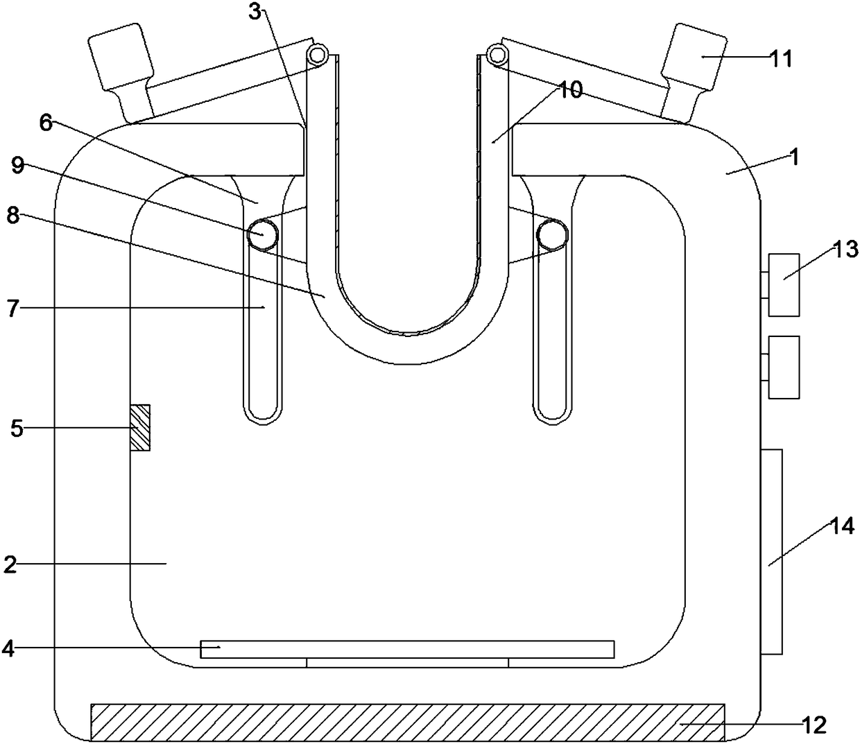
[0014] Embodiment 1: When a test tube rack is used to fix the test tube, a test tube rack for medical examination includes a base 1, a water tank 2 is arranged inside the base 1, and a through hole 3 through the water tank 2 is provided on the upper surface of the base 1, and the water tank 2 is provided on the upper surface of the base 1. The inner bottom surface of the tank 2 is fixedly connected with a heating device 4, the middle part of the left side wall of the water tank 2 is fixedly connected with a temperature sensing element 5, and the inner top surface of the water tank 2 is located on the left and right sides of the through hole 3 and is fixedly connected with the support plate 6, and the support plate 6 The front side is provided with a penetrating movable groove 7, and the inside of the water tank 2 is provided with a clip seat 8, the left and right outer walls of the clip seat 8 are fixedly connected to the slider 9 near the bottom, and the slider 9 is movably con...

Embodiment 2

[0018] Embodiment 2: When not in use, a test tube rack for medical examination, including a base 1, is characterized in that: the inside of the base 1 is provided with a water tank 2, and the upper surface of the base 1 is provided with a through hole 3 passing through the water tank 2, The inner bottom surface of the water tank 2 is fixedly connected with a heating device 4, and the middle part of the left side wall of the water tank 2 is fixedly connected with a temperature sensing element 5. 6. The front side is provided with a penetrating movable groove 7, and the interior of the water tank 2 is provided with a clip seat 8, and the left and right side walls of the clip seat 8 are fixedly connected to the slider 9 near the bottom, and the slider 9 is movably connected in the movable groove 7, and the clip seat The left and right side wall tops of 8 are respectively hinged with a splint 10, the top of the splint 10 is fixedly connected with a chuck 11, the inner bottom surfac...


PUM


Abstract

The invention relates to the technical field of mechanical instruments, in particular to a test-tube stand for medical examination. A water sump is arranged inside a base; a through hole penetrating through the water sump is formed in the upper surface of the base; a temperature sensing element is fixedly connected to the middle part of the left side wall of the water sump; supporting plates are fixedly connected to the left side and the right side of the through hole in the inner top surface of the water sump; a penetrating movable groove is formed in the front side of each supporting plate;the base comprises a base body, connectors and circuit connecting holes; the connectors are arranged at the relative upper part of the base body; the circuit connecting holes are formed in the relative side parts of the base body; a plurality of connectors are arranged and each connector comprises a connector elastic clip telescopic part and a connector body; each connector body is connected withthe base body by the corresponding connector elastic clip telescopic part; a display comprises a display body; a wire casing which is independent of an electronic component area of the display body isformed in the back side of the display body; the wire casing is provided with a plurality of wire outlets; a wire clamping structure is arranged in each wire casing.

Description

technical field [0001] The invention relates to the technical field of medical instruments, in particular to a test tube rack for medical inspection. Background technique [0002] Medical examination is a discipline that uses modern physical and chemical methods and means to conduct medical diagnosis. It mainly studies how to provide evidence for clinical diagnosis and treatment through laboratory technology and medical equipment. Through systematic learning, we will learn how to identify a person's blood type, determine whether a person is anemic, whether the liver function is normal, and so on. This subject requires the use of various photoelectric instruments and chemical reagents to complete experimental analysis, so it emphasizes science and requires a good foundation in biology and chemistry. [0003] At present, a large number of test tubes are used in medical testing. Most of the test tubes used now are of glass tube structure. The surface of this glass tube is rela...

Claims


Application Information

Patent Timeline
Patent Type & Authority Applications(China)
IPC IPC(8): B01L9/06B01L7/00
CPCB01L9/06B01L7/00B01L2200/147B01L2300/185
Inventor 李文文
Owner 李文文
Why Eureka
Try Eureka