Laser engraving machine

A laser engraving machine and laser engraving technology, applied in the direction of laser welding equipment, auxiliary equipment, auxiliary welding equipment, etc., can solve the problems of poor engraving effect and poor positioning effect of the workpiece, and achieve the guaranteed effect and the guaranteed limit effect Effect

Inactive Publication Date: 2018-05-29
重庆鑫盟精密模具有限公司
View PDF8 Cites 4 Cited by
  • Summary
  • Abstract
  • Description
  • Claims
  • Application Information

AI Technical Summary

Problems solved by technology

[0004] The present invention intends to provide a laser engraving machine to solve the problem that the current laser engraving device affects the poor engraving effect of the workpiece due to the poor positioning effect of the workpiece

Method used


Image

  • Laser engraving machine

Examples


Embodiment Construction

[0019] Further detailed explanation through specific implementation mode below:

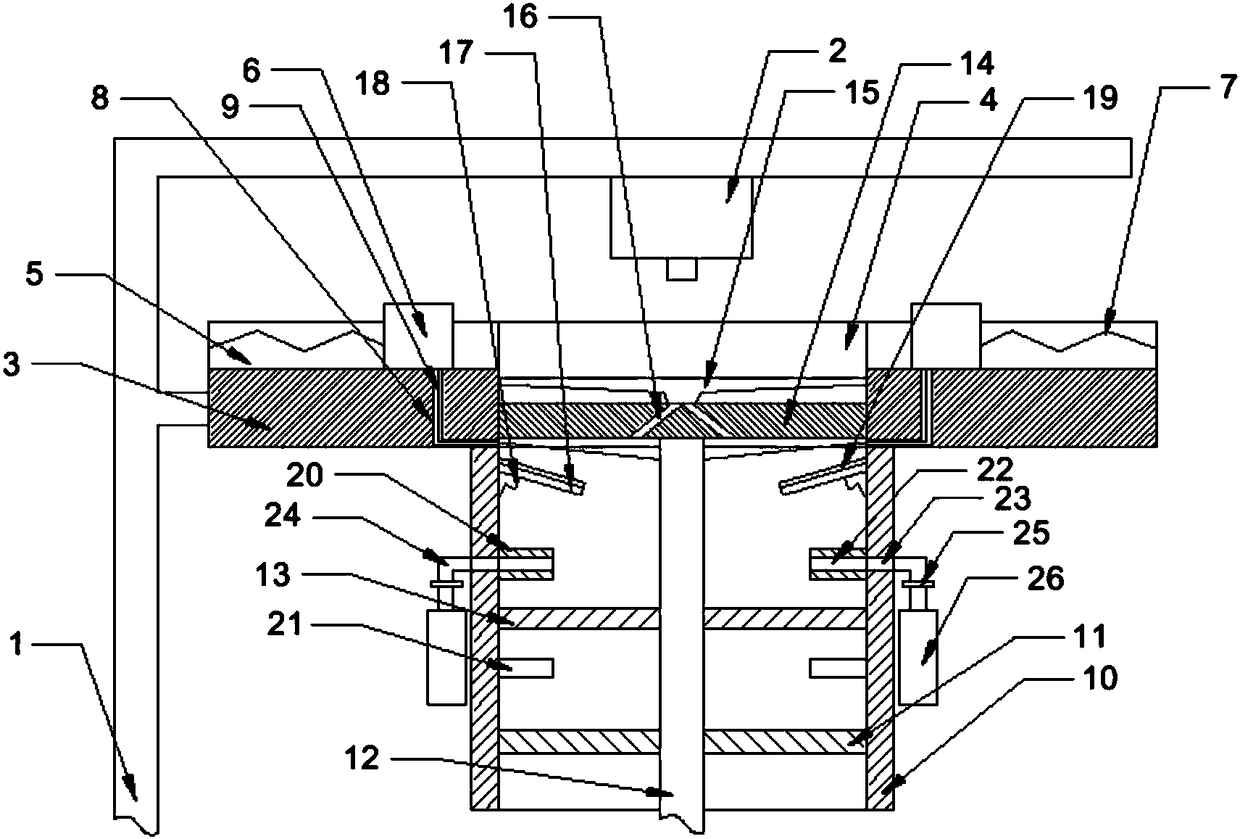
[0020] The reference signs in the drawings of the description include: machine base 1, laser engraving head 2, support plate 3, round hole 4, chute 5, slider 6, first spring 7, through hole 8, iron wire 9, sleeve 10 , fixed plate 11, threaded rod 12, iron plate 13, holding plate 14, suction cup 15, air hole 16, rocker arm 17, second spring 18, rubber layer 19, upper magnet 20, lower magnet 21, discharge hole 22, Side hole 23, discharge pipe 24, one-way valve 25, collection box 26.

[0021] The embodiment is basically as attached figure 1 Shown: a kind of laser engraving machine, comprises machine base, and laser engraving head 2 is installed on the machine base; Support plate 3 is welded on the machine base, and the center of support plate 3 is provided with circular hole 4, and circular hole 4 is connected with laser engraving Head 2 is vertically opposite. The support plate 3 is provided wit...


PUM


Abstract

The invention discloses a laser engraving machine. The laser engraving machine comprises a machine base; a laser engraving head is arranged on the machine base; a supporting plate is arranged on the machine base; a round hole is formed in the center of the supporting plate and is opposite to the laser engraving head in the vertical direction; sliding grooves are symmetrically formed in the supporting plate; sliding blocks are arranged in the sliding grooves in a sliding mode; first springs are arranged between the sliding blocks and the sliding grooves; through holes are formed in the bottom parts of the sliding grooves; iron wires penetrating through the through holes are arranged on the sliding blocks; hollow sleeves are arranged at the bottom part of the supporting plate; a fixing plateis fixedly connected in the sleeves; a threaded rod is connected to the fixing plate in a threaded mode; an iron plate is arranged on the threaded rod; a containing plate is arranged on the threadedrod; a sucker is arranged on the containing plate, and an air hole is formed in the containing plate; the iron wire are fixedly connected to the threaded rod;and buffering mechanisms used for adjusting the position of the containing plate and positioning mechanisms used for stopping the iron plate are arranged on the inner walls of the sleeves. According to the laser engraving machine, the problemthat an existing laser engraving device is poor in workpiece engraving effect due to poor positioning effect on a workpiece can be mainly solved.

Description

technical field [0001] The invention relates to the technical field of processing with lasers. Background technique [0002] Laser engraving is based on numerical control technology, and laser is the processing medium. The physical denaturation of the instant melting and gasification of the processing material under the irradiation of laser engraving can make laser engraving achieve the purpose of processing. Laser engraving is the use of laser technology to engrave text on objects. The characters engraved by this technology have no notches, the surface of the object is still smooth, and the writing will not wear out. [0003] When the laser engraving device is in use, it is necessary to position the workpiece first, and then perform laser engraving on the workpiece. At present, the laser engraving device mainly realizes the positioning of the workpiece in two relative directions, so that the positioning effect of the workpiece is not good, which will directly affect the e...

Claims


Application Information

Patent Timeline
Patent Type & Authority Applications(China)
IPC IPC(8): B23K26/362B23K26/70B23K37/04
CPCB23K26/361B23K26/70B23K37/04
Inventor 吕献平
Owner 重庆鑫盟精密模具有限公司
Why Eureka
Try Eureka