
Testing system

A test system and test device technology, applied in the direction of aircraft component testing, etc., can solve problems such as uncontrollable ambient temperature, required execution of test methods, low test efficiency, etc., and achieve the effects of avoiding detonation risk, low cost, and improving safety.

Active Publication Date: 2018-05-29
广电计量检测(无锡)有限公司
View PDF6 Cites 1 Cited by
  • Summary
  • Abstract
  • Description
  • Claims
  • Application Information

AI Technical Summary

Problems solved by technology

[0003] At present, the detection mechanism generally uses two independent test devices to detect the check valve and the injection pump respectively, and the test efficiency is low. Moreover, the existing test device separates the fuel temperature control work from the ambient temperature test. The test method Also can not be carried out completely according to the requirement of industry testing standard DO-160G, and its applicability in the market is less; In addition, check valve is generally placed in the rapid temperature change box in the prior art, and check valve's There is a risk of oil leakage at both ends, and the heating wire works when the rapid temperature change box heats up, which may easily reach the flash point of the fuel and cause a safety accident; and the existing test device for the injection pump of the airborne fuel tank, the injection pump is half of the working time. Submerged in the oil of the oil tank, the other half is exposed to the environment, so the performance of the ejection pump can only be tested by changing the test oil temperature, and the ambient temperature cannot be controlled, so that the test does not meet the requirements of the industry standard

Method used


Image

  • Testing system

Examples


Embodiment Construction

[0025] The following will clearly and completely describe the technical solutions in the embodiments of the present invention with reference to the accompanying drawings in the embodiments of the present invention. Obviously, the described embodiments are only some, not all, embodiments of the present invention. Based on the embodiments of the present invention, all other embodiments obtained by persons of ordinary skill in the art without creative efforts fall within the protection scope of the present invention.

[0026] It should be understood that the terms "first", "second", etc. are used in the present invention to describe various information, but these information should not be limited to these terms, and these terms are only used to distinguish information of the same type from each other. For example, "first" information may also be referred to as "second" information without departing from the scope of the present invention, and similarly, "second" information may al...


PUM


Abstract

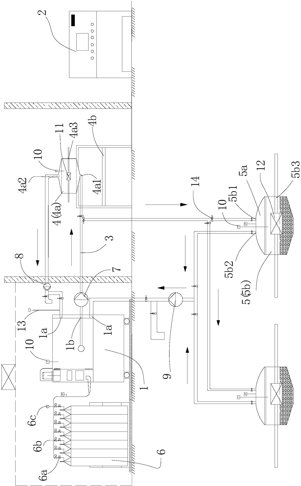
The invention provides a testing system. The testing system comprises a temperature control system, a nitrogen system, a control system, a first testing device for testing a one-way valve and a secondtesting device for testing a jet pump. The temperature control system, the nitrogen system, the first testing device and the second testing device are electrically connected with the control system.The temperature control system comprises a rapid temperature change box, the nitrogen system is connected with the rapid temperature change box, and the rapid temperature change box is provided with an air inlet end and an air outlet end. A first air inlet and a first air outlet are formed in the first testing device, the second testing device is provided with a second air inlet and a second air outlet, and the first air inlet and the second air inlet communicate with the air outlet end through heat-insulating pipelines correspondingly. The heat insulating pipelines are provided with circulating draught fan systems. By adoption of the testing system of the technical scheme, the testing efficiency of the testing system is high, the requirement of industry detecting standards is met, and thesafety of the testing process can be ensured.

Description

technical field [0001] The invention relates to the field of detection of airborne fuel tanks, in particular to a testing system. Background technique [0002] C919 (full name COMAC C919) large passenger aircraft is a large jet civil aircraft developed by my country in accordance with international civil aviation regulations and has independent intellectual property rights. It has 158-168 seats and a range of 4075-5555 kilometers. . With the successful development of C919, the testing and requirements of aircraft components have become more stringent. As part of the aircraft fuel system, check valves and onboard fuel tank injection pumps have a great impact on the performance of the aircraft and the safety of the aircraft during use. It has a great influence, and the corresponding industry test standard (D0-160G) also strictly limits the testing standards of each component. [0003] At present, the detection mechanism generally uses two independent test devices to detect th...

Claims


Application Information

Patent Timeline
Patent Type & Authority Applications(China)
IPC IPC(8): B64F5/60
CPCB64F5/60
Inventor 刘红高罗平杨子亮杜泽宁
Owner 广电计量检测(无锡)有限公司
Learn More