Standing pouch tube sealing machine pouch protecting frame

A technology of stand-up pouch and tube sealing machine, which is applied in packaging and other directions, can solve the problems of stand-up pouch deviation, affect bagging accuracy, and affect the appearance of stand-up pouches, and achieve the effect of improving the quality of finished products and reducing the rate of defective products

Pending Publication Date: 2018-05-29
GBPI PACKAGING TEST INSTR
View PDF12 Cites 0 Cited by
  • Summary
  • Abstract
  • Description
  • Claims
  • Application Information

AI Technical Summary

Problems solved by technology

[0005] When the traditional tube sealing machine transports the stand-up pouch, it adopts the method of horizontal placement, embeds the two sides of the stand-up pouch on the blocks on both sides of the stand-up pouch, and then transports it to the sealing equipment. The slot for fixing the straw is located on the sealing device, so when the stand-up pouch is transported to a position opposite to the straw, a pushing mechanism is required to push the stand-up pouch toward the straw so that it is nested outside the straw and then heat-pressed , the mechanism for fixing the stand-up pouch and the mechanism for fixing the straw are split structures, so when the stand-up pouch is transported to the straw station, there will be a certain error between the sealing edge and the straw, and the straw cannot heat seal the straw accurately At the position where the heat seal is required, it will be offset relative to the stand-up pouch, which will not only affect the appearance of the stand-up pouch, but also affect the accuracy of subsequent bagging

Method used


Image

  • Standing pouch tube sealing machine pouch protecting frame
  • Standing pouch tube sealing machine pouch protecting frame
  • Standing pouch tube sealing machine pouch protecting frame

Examples


Embodiment 1

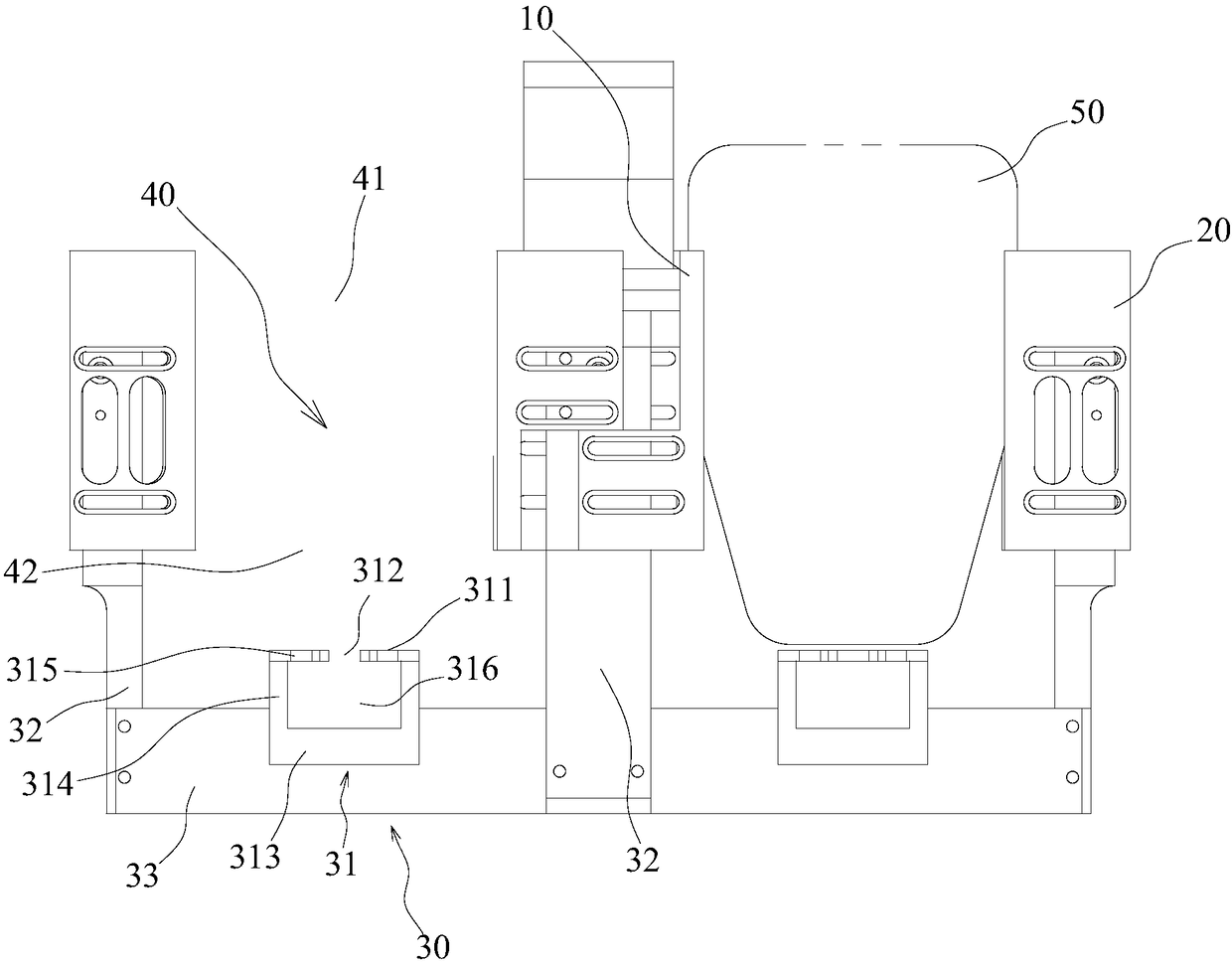
[0044] Embodiment 1: as Figure 1~4 As shown, the first guide groove 11 and the second guide groove 21 are parallel to each other, and both are perpendicular to the horizontal plane.

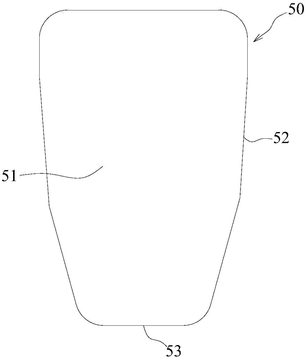
[0045] Preferably, the distances between the opening 312 and the first guiding groove 11 and the second guiding groove 21 are equal. This embodiment is mostly used for the stand-up pouch 50 structure in which the straw is located in the middle of the sealing edge 53 of the stand-up pouch 50, and the distance between the opening 312 and the first guide groove 11 is equal to the distance between the opening 312 and the second guide groove 21. When the bag 50 enters the positioning space 40 from the bag-entry end 41, it is vertically displaced in the direction of the opening 312 along the setting direction of the first guide groove 11 and the second guide groove 21, so that both sides 52 of the stand-up bag 50 are vertical after the straw is nested. On a horizontal plane, the suction pipe can also...

Embodiment 2

[0046] Embodiment 2: as figure 1 , Figure 5-7 As shown, the first guide groove 11 is inclined relative to the horizontal plane, so that the extension line of the first guide groove 11 intersects the extension line of the second guide groove 21 and forms a positioning point (not shown);

[0047] The positioning point is located between the first guide groove 11 and the second guide groove 21, and is located below the first guide groove 11 and the second guide groove 21; here, since the first guide groove 11 is inclined relative to the horizontal plane, the stand-up bag 50 When entering the positioning space 40 from the bag-entry end 41, the side edge 52 of the stand-up bag 50 close to the first guide groove 11 is also inclined together with the first guide groove 11, so the extension line of the first guide groove 11 is aligned with the second guide groove. The intersection point of the extension line of 21 becomes the supporting end of the stand-up bag 50, so that the sealin...


PUM


Abstract

The invention discloses a standing pouch tube sealing machine pouch protecting frame and relates to a heat sealing machine component. The standing pouch tube sealing machine pouch protecting frame comprises a positioning assembly and a supporting assembly, the positioning assembly is located above the supporting assembly and used for guiding the side face of a standing pouch to be placed perpendicular to the horizontal plane, and the supporting assembly comprises a supporting block with the surface provided with a supporting face for supporting the tube sealing edge of the standing pouch. Thesupporting face is provided with an opening for positioning a suction tube. The pouch protecting frame enables the suction tube to be positioned more precisely relative to the standing pouch in the heat sealing process for the standing pouch and the suction tube, subsequent process requirements are met, and the rejection rate is reduced. The positioning assembly can be regulated to regulate the position of the suction tube relative to the standing pouch, and thus different packaging requirements are met.

Description

technical field [0001] The invention relates to a heat sealing machine part, in particular to a bag protection frame for a stand-up pouch tube sealing machine. Background technique [0002] Tube sealing machine is also called stand-up pouch nozzle welding machine, nozzle bag sealing machine, automatic tube sealing machine, etc. It is a packaging machine for heat-sealing straws for stand-up pouches with nozzles or straws. It is mainly widely used in fluid products such as beverages, fruit juices, and fabric softeners, and can also be used in granular / powder products such as chicken powder, monosodium glutamate, and salt. [0003] Such as figure 1 As shown, the stand-up pouch includes a main body and a straw, and the main body includes two sides of the stand-up pouch heat-pressed; wherein, one side of the stand-up pouch forms a sealing edge for heat-compression fit with the straw. [0004] However, the existing heat-sealing structure of the tube sealing machine has the foll...

Claims


Application Information

Patent Timeline
Patent Type & Authority Applications(China)
IPC IPC(8): B65B61/20
CPCB65B61/205
Inventor 周学惠肖旭
Owner GBPI PACKAGING TEST INSTR
Why Eureka
Try Eureka