
Ink scraper clamping and quenching device for quenching furnace

A technology of quenching device and quenching furnace, applied in the direction of quenching device, furnace, furnace type, etc., can solve the problems of low operation efficiency of ink scraper, inconvenient ink scraper clamping, etc.

Inactive Publication Date: 2018-05-29
SUZHOU ZHONGXINYUAN MICROELECTRONICS CO LTD
View PDF2 Cites 0 Cited by
  • Summary
  • Abstract
  • Description
  • Claims
  • Application Information

AI Technical Summary

Problems solved by technology

The quenching device is inconvenient to clamp the ink scraper, and the efficiency of quenching the ink scraper is low

Method used


Image

  • Ink scraper clamping and quenching device for quenching furnace

Examples


Embodiment Construction

[0015] The specific implementation manners of the present invention will be further described below in conjunction with the drawings and examples. The following examples are only used to illustrate the technical solution of the present invention more clearly, but not to limit the protection scope of the present invention.

[0016] The technical scheme of concrete implementation of the present invention is:

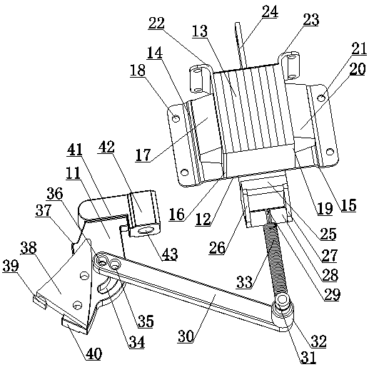
[0017] Such as figure 1 As shown, a kind of ink scraper clamping and quenching device for quenching furnace includes a base plate 11 and a base plate 12, and the base plate 12 is provided with several clamping pieces 13, and there are clamping grooves between two adjacent clamping pieces 13. The top surface of base plate 12 is provided with first clamping plate 16, and the back of first clamping plate 16 is provided with first clamping seat 17, and first clamping seat 17 is installed on the top surface of base plate 12, and the top surface of base plate 12 There is a sec...


PUM


Abstract

The invention discloses an ink scraper clamping and quenching device for a quenching furnace. The ink scraper clamping and quenching device comprises a substrate and a base plate, wherein a pluralityof clamping pieces are arranged on the base plate; a clamping groove is formed between every two adjacent clamping pieces; clamping plates are arranged on the top surface of the base plate; a clampingseat is arranged at the back of each clamping plate and is arranged on the top surface of the base plate; the plurality of clamping pieces are arranged between the clamping plates; a connecting casing is arranged at the front part of the base plate; side plates are arranged at one side of the connecting casing; a butting pipe is arranged between front parts of the side plates; a hook groove is formed in the outer circumferential surface of the middle part of the butting pipe; an adjusting arm is arranged on the substrate; one end of the adjusting arm is connected with the substrate; a connecting spring is connected to the other end of the adjusting arm; one end of the connecting spring is connected with the other end of the adjusting arm; the other end of the connecting spring sleeves thehook groove. According to the ink scraper clamping and quenching device disclosed by the invention, an ink scraper is clamped between the clamping pieces; the clamping seats can be used for clampingcertain sides of the clamping pieces, which is convenient for the quenching furnace to carry out quenching treatment on the ink scraper.

Description

technical field [0001] The invention relates to a clamping and quenching device, in particular to a clamping and quenching device for an ink scraper used in a quenching furnace. Background technique [0002] In the prior art, such as the patent ZL201020593479.1 discloses a local quenching device, including a frame, the frame is equipped with a main shaft, the main shaft is lifted and lowered by the lifting gear, and the local quenching height is automatically positioned, and the table of the main shaft is provided with a chuck There is an induction coil above the chuck, and the induction coil measures the temperature through infrared temperature measuring equipment, and the temperature measurement data is displayed through the control cabinet, and the rack is adjusted to move up and down on the column through gears. Another example is patent ZL201420614399.8, which discloses a high-frequency quenching device for shaft steering knuckle journals, which includes a tray, and a...

Claims


Application Information

Patent Timeline
IPC IPC(8): C21D1/62C21D9/18
CPCC21D1/62C21D9/18Y02P10/20
Inventor 王丽萍
Owner SUZHOU ZHONGXINYUAN MICROELECTRONICS CO LTD
Learn More