
Underground storage tank structure for liquefied natural gas and construction method thereof

A technology for liquefied natural gas and underground storage tanks, which is applied in the field of liquefied natural gas underground storage tank structure and its construction, can solve the problems of LNG underground storage tank technology and lack of development, solve the problem of tank structure cracking, improve engineering economic benefits and Social and economical benefits

Inactive Publication Date: 2018-05-29
ZHONGCHUAN NO 9 DESIGN & RES INST
View PDF5 Cites 2 Cited by
  • Summary
  • Abstract
  • Description
  • Claims
  • Application Information

AI Technical Summary

Problems solved by technology

LNG underground storage tanks (including semi-underground storage tanks, etc.) are widely used in the world. The operation of underground storage tanks and semi-underground storage tanks in Japan and South Korea is good. However, limited by economic and technical constraints, my country's The technology and development of LNG underground storage tanks are still lacking

Method used


Image

  • Underground storage tank structure for liquefied natural gas and construction method thereof
  • Underground storage tank structure for liquefied natural gas and construction method thereof
  • Underground storage tank structure for liquefied natural gas and construction method thereof

Examples


Embodiment 1

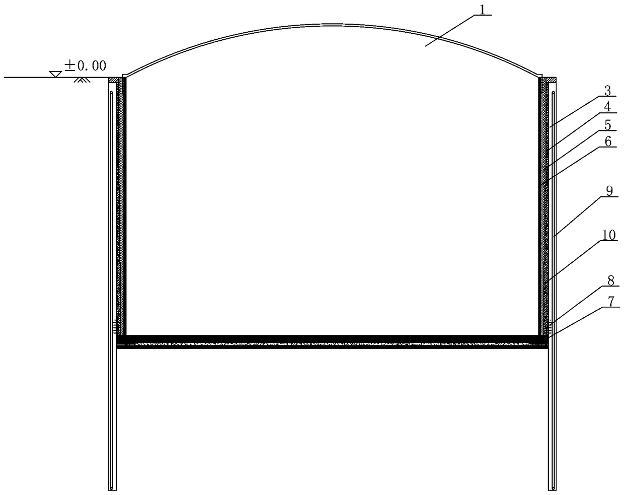
[0023] Through calculation and analysis, it is determined that the thickness of the underground diaphragm wall 3 is 1.5m, and the insertion depth is 30.0m. The specific construction is carried out according to the following steps:

[0024] (1) Construction of foundation pit enclosure structure

[0025] The construction of the underground diaphragm wall 3 includes trough forming, steel cage fabrication and hoisting, layout and embedding of embedded parts (wall bottom grouting pipelines, wall side grouting pipelines and lining connecting steel bars), underwater concrete pouring and other processes. Combined with the technical requirements of the outer tank of the LNG underground storage tank 1, the grouting pipe 9 is pre-embedded in the underground diaphragm wall 3, and the corresponding steel bar stress sensor is pre-embedded in the steel cage.

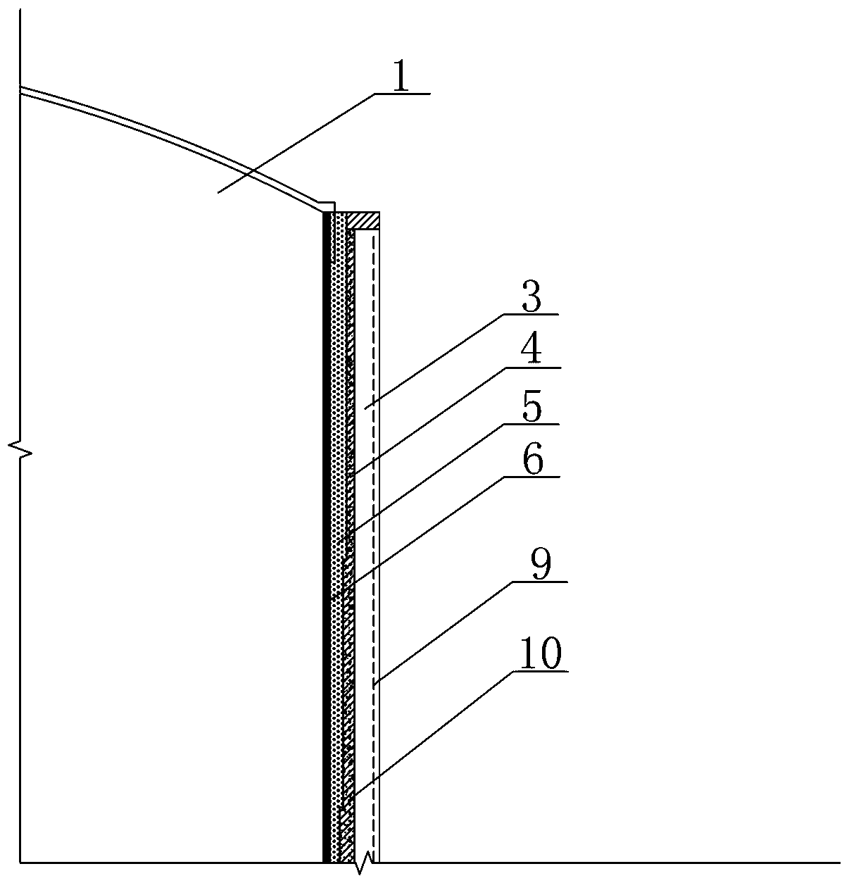
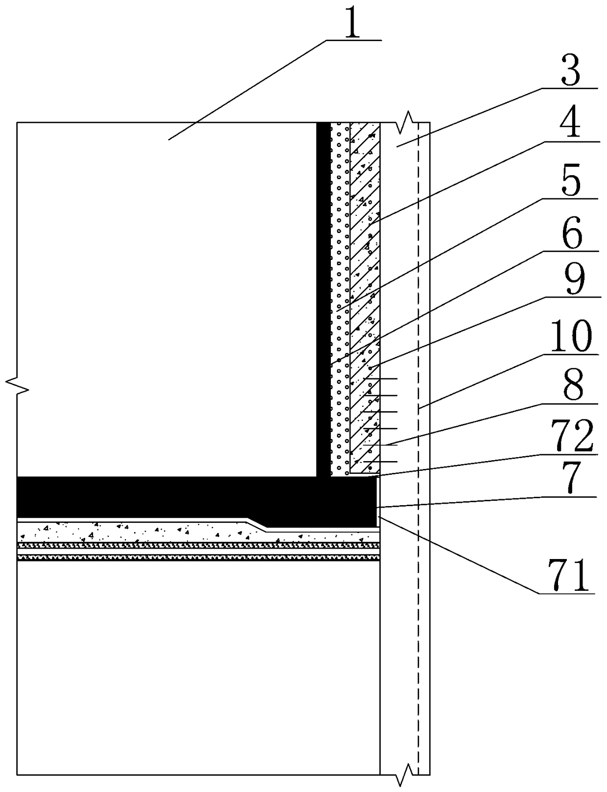
[0026] (2) Construction of inner wall

[0027] See attached figure 2 , the inner lining wall 4 is stepped and the tank body insula...


PUM


Abstract

The invention discloses an underground storage tank structure for liquefied natural gas and a construction method thereof. The underground storage tank structure for liquefied natural gas is characterized in that an underground diaphragm wall and a lining wall jointly form an outer tank structure of a prestressed wall, the outer tank structure, an inner tank body and a heat-insulating layer form atank structure of an LNG (liquefied natural gas) underground storage tank, the lining wall is disposed on a bottom plate, the bottom of the lining wall is connected with the underground diaphragm wall through anti-shear connection keys; a vertical settlement joint is arranged between the bottom plate and the underground diaphragm wall; a transverse settlement joint is arranged between the bottomplate and the lining wall; a prestressed wall structure for annular pressure grouting is arranged outside the underground diaphragm wall. The construction method comprises the specific steps of reversely constructing the lining wall along with excavation of soil, constructing the bottom plate, and constructing the inner tank body and the heat-insulating layer. Compared with the prior art, the underground storage tank structure for liquefied natural gas and the construction method thereof have the advantages that safety is high, economy is good, small space is used, working efficiency is high,free settlement under full tank condition can be met, bulging of the inner tank under empty tank condition can also be controlled, and the tank structure cracking problem due to local stress concentration and fatigue cycle is well solved.

Description

technical field [0001] The invention relates to the technical field of building underground space excavation, in particular to a liquefied natural gas underground storage tank structure combined with an underground continuous wall and a construction method thereof. Background technique [0002] As the proportion of LNG (liquefied natural gas) as my country's primary energy increases year by year, the consumption ratio of LNG (liquefied natural gas) will increase from 6.8% to 10% by 2020. Since 2016, the progress of LNG (liquefied natural gas) receiving stations has been significantly accelerated. my country plans to build hundreds of large LNG (liquefied natural gas) storage tanks in the near future. LNG underground storage tanks (including semi-underground storage tanks, etc.) are widely used in the world. The operation of underground storage tanks and semi-underground storage tanks in Japan and South Korea is good. However, limited by economic and technical constraints, my...

Claims


Application Information

Patent Timeline
Patent Type & Authority Applications(China)
IPC IPC(8): E02D29/05F17C5/02
CPCF17C5/02E02D29/05F17C2223/013F17C2203/0678F17C2209/00
Inventor 金国龙林靖王鑫李昀周竝王勇符晓赟
Owner ZHONGCHUAN NO 9 DESIGN & RES INST
Learn More