Mobile LPG bottle group gasification device and gasification method thereof

A gasification device and mobile technology, applied in the field of LPG gasification, can solve the problems of inability to meet mobile gas supply, poor mobile performance, etc., and achieve the effects of ensuring safety, favorable production and convenient management

Active Publication Date: 2018-05-29
四川华气清源科技股份有限公司
View PDF5 Cites 0 Cited by
  • Summary
  • Abstract
  • Description
  • Claims
  • Application Information

AI Technical Summary

Problems solved by technology

[0004] The technical problem to be solved by the present invention is: the existing LPG bottle group gasification stations are all fixedly installed, the mobile performance is not good, and the demand for mobile gas supply cannot be met. The purpose is to provide a mobile gasification station to solve the above problems Type LPG bottle group gasification device and gasification method thereof

Method used


Image

  • Mobile LPG bottle group gasification device and gasification method thereof

Examples


Embodiment 1

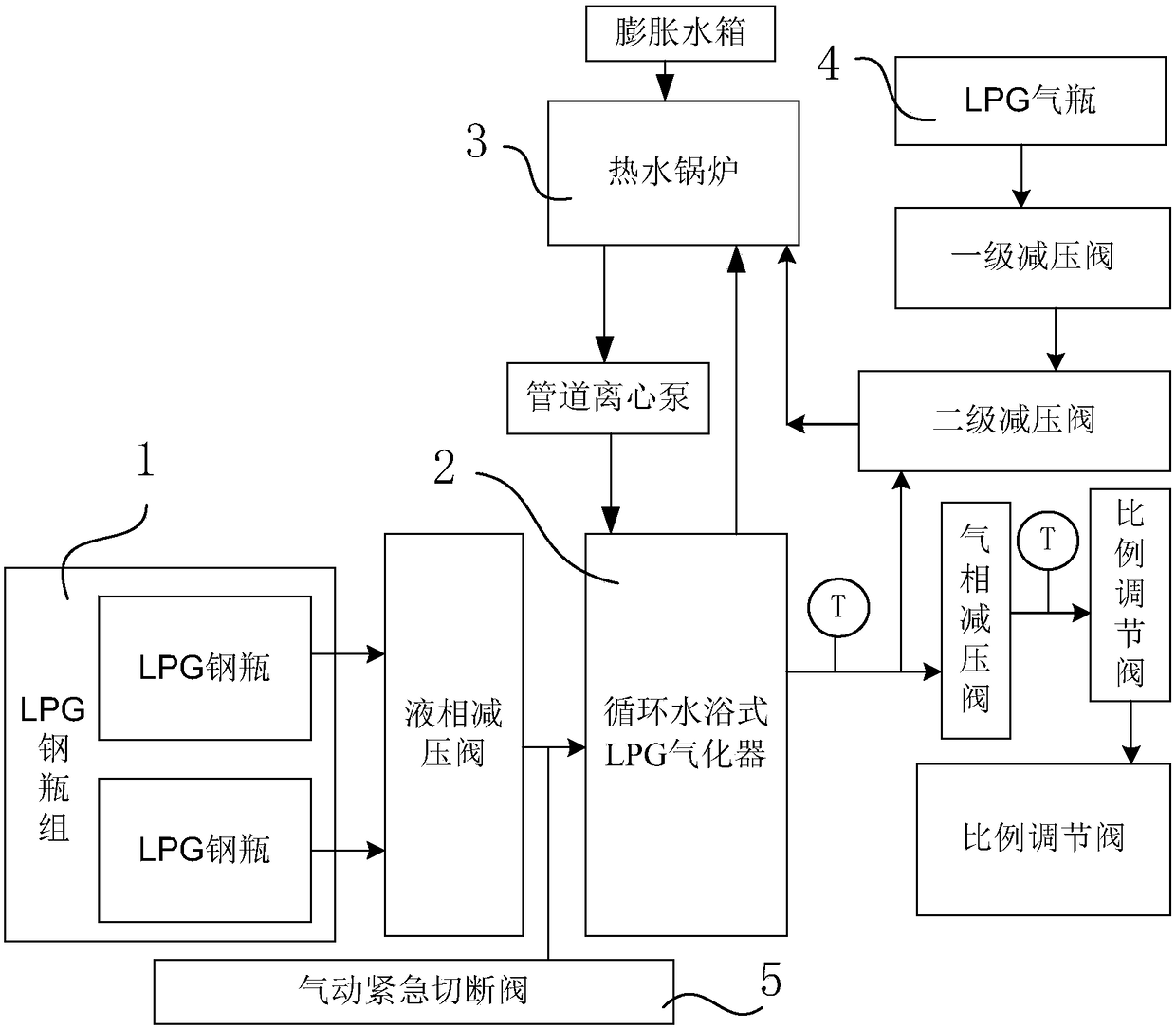
[0040] A mobile LPG bottle group gasification device, such as figure 1 As shown, it includes the LPG cylinder group 1, the circulating water-bath LPG gasifier 2 that communicates with the LPG cylinder group 1 through the main pipeline and provides users with gas phase gas, and the hot water boiler that provides hot water for the circulating water-bath LPG gasifier 2 3. The LPG gas cylinder 4 that provides combustion energy for the hot water boiler 3 .

[0041] In this embodiment, the hot water boiler 3 has an inlet pipe, a water inlet pipe, a water outlet pipe and a return water pipe, and the circulating water bath type LPG vaporizer 2 has a water inlet pipe, a liquid inlet pipe, a water outlet pipe and a gas outlet pipe.

[0042] The water inlet pipe of the circulating water bath type LPG gasifier 2 is connected with the water outlet pipe of the hot water boiler 3, and the water outlet pipe of the circulating water bath type LPG gasifier 2 is connected with the return water p...

Embodiment 2

[0045] The difference between this embodiment and Embodiment 1 is that the structure before and after the circulating water bath type LPG gasifier 2 is further optimized in this embodiment, and the specific settings are as follows:

[0046] The liquid inlet pipeline of the circulating water bath type LPG gasifier 2 communicates with the LPG cylinder group 1 through the liquid phase pressure reducing valve, and the gas phase pressure reducing valve is also arranged on the gas outlet pipeline of the circulating water bath type LPG gasifier 2, and the liquid phase reducing The pressure of the pressure valve output liquid is 0.1-0.3Mpa, and the pressure of the gas-phase pressure reducing valve output gas is 13-15Kpa. In this embodiment, the pressure of the output liquid from the liquid phase pressure reducing valve is preferably 0.2Mpa, and the pressure of the gas output from the gas phase pressure reducing valve is preferably 14Kpa.

[0047] Through the setting of the above struc...

Embodiment 3

[0049] The difference between this embodiment and Embodiment 2 is that this embodiment further optimizes the structural settings, and the specific settings are as follows:

[0050] Such as figure 1 As shown, the outlet pipeline of the LPG cylinder 4 is connected with a primary pressure reducing valve and a secondary pressure reducing valve in sequence, and the outlet of the secondary pressure reducing valve communicates with the intake pipeline of the hot water boiler 3 . The gas outlet pipeline of the circulating water bath type LPG gasifier 2 is sequentially connected with a gas phase pressure reducing valve and a proportional regulating valve, and the inlet of the gas phase pressure reducing valve is also communicated with the inlet of the secondary pressure reducing valve. An emergency shut-off valve 5 is arranged on the main pipeline, and a temperature transmitter interlocked with the emergency shut-off valve 5 is also arranged on the gas outlet of the circulating water b...


PUM


Abstract

The invention discloses a mobile LPG bottle group gasification device, and solves the problems that existing LPG bottle group gasification stations are all fixedly installed, have poor mobility, and cannot meet demands of mobile gas supply. The mobile LPG bottle group gasification device comprises an LPG steel cylinder group, a circulating water bath type LPG vaporizer communicating with the LPG steel cylinder group through a main pipeline and providing gas phase gas to a user, a hot water boiler providing hot water for the circulating water bath type LPG vaporizer, an LPG gas cylinder providing combustion energy for the hot water boiler; and a gas outlet pipeline of the circulating water bath type LPG vaporizer communicates with a gas inlet pipeline of the hot water boiler. Under the premise of paying attention to safety, the mobile LPG bottle group gasification device can well achieve a purpose of mobile gas supply and ensure that the output gas volume meets an industrial productiondemand.

Description

technical field [0001] The invention belongs to the field of LPG gasification, and in particular relates to a mobile LPG bottle group gasification device and a gasification method thereof. Background technique [0002] The existing technology is a conventional fixed LPG bottle group gasification station, and its structure usually includes a gas collection bottle for one standby and one for use, a gasifier for converting the LPG in the gas collection bottle into a gas phase, and the vaporized gas After decompression, it is sent to the user's pressure reducing valve. [0003] The structure composed of the above-mentioned LPG bottle group, pipeline, and gasifier is all fixed installation, and the mobile performance is not good, so it cannot meet the needs of mobile gas supply. Contents of the invention [0004] The technical problem to be solved by the present invention is: the existing LPG bottle group gasification stations are all fixedly installed, the mobile performance ...

Claims


Application Information

Patent Timeline
Patent Type & Authority Applications(China)
IPC IPC(8): F17C7/04F17C13/02
CPCF17C7/04F17C13/025F17C13/026F17C2227/0316
Inventor 林为民庞瑞涛陈刚
Owner 四川华气清源科技股份有限公司
Why Eureka
Try Eureka