
Liquid crystal display panel with operation sensing function and display device thereof

A liquid crystal display panel and display device technology, which is applied in the input/output process of data processing, optics, instruments, etc., can solve the problem that the touch signal cannot be sensed smoothly, the touch electrode layer cannot be arranged below the liquid crystal layer, and the touch display Panel cost advantage, fit rate, thinness and line consistency decrease, etc.

Inactive Publication Date: 2018-05-29
TENX (SHENZHEN) TECH LTD +1
View PDF5 Cites 4 Cited by
  • Summary
  • Abstract
  • Description
  • Claims
  • Application Information

AI Technical Summary

Problems solved by technology

[0003] Since at least one additional touch electrode layer is required to sense the touch signal, and an additional insulating substrate is required to be bonded to the liquid crystal display panel, the above-mentioned touch display panel has advantages in cost, bonding rate, lightness and wiring The consistency will decrease relatively
On the other hand, the above-mentioned additional touch electrode layer cannot be disposed under the liquid crystal layer, otherwise the touch signal will not be successfully sensed, therefore, the degree of freedom to choose the position where the above-mentioned touch electrode layer can be placed is reduced.
[0004] In addition, although an in-cell touch display panel structure has been proposed, it still needs to use at least one additional touch electrode layer to sense the touch signal, and it is still The process steps of the original liquid crystal display panel must be greatly changed in order to successfully manufacture the in-cell touch display panel

Method used


Image

  • Liquid crystal display panel with operation sensing function and display device thereof
  • Liquid crystal display panel with operation sensing function and display device thereof
  • Liquid crystal display panel with operation sensing function and display device thereof

Examples


Embodiment Construction

[0036] Various exemplary embodiments will be described more fully hereinafter with reference to the accompanying drawings, in which some exemplary embodiments are shown. However, the disclosed concepts may be embodied in many different forms and should not be construed as limited to the exemplary embodiments set forth herein. Rather, these exemplary embodiments are provided so that this disclosure will be thorough and complete, and will fully convey the scope of the disclosed concept to those skilled in the art. In the drawings, the size and relative sizes of layers and regions may be exaggerated for clarity. Like numerals indicate like elements throughout, and the term "or" as used herein may include all combinations of any one or more of the associated listed items, as the case may be.

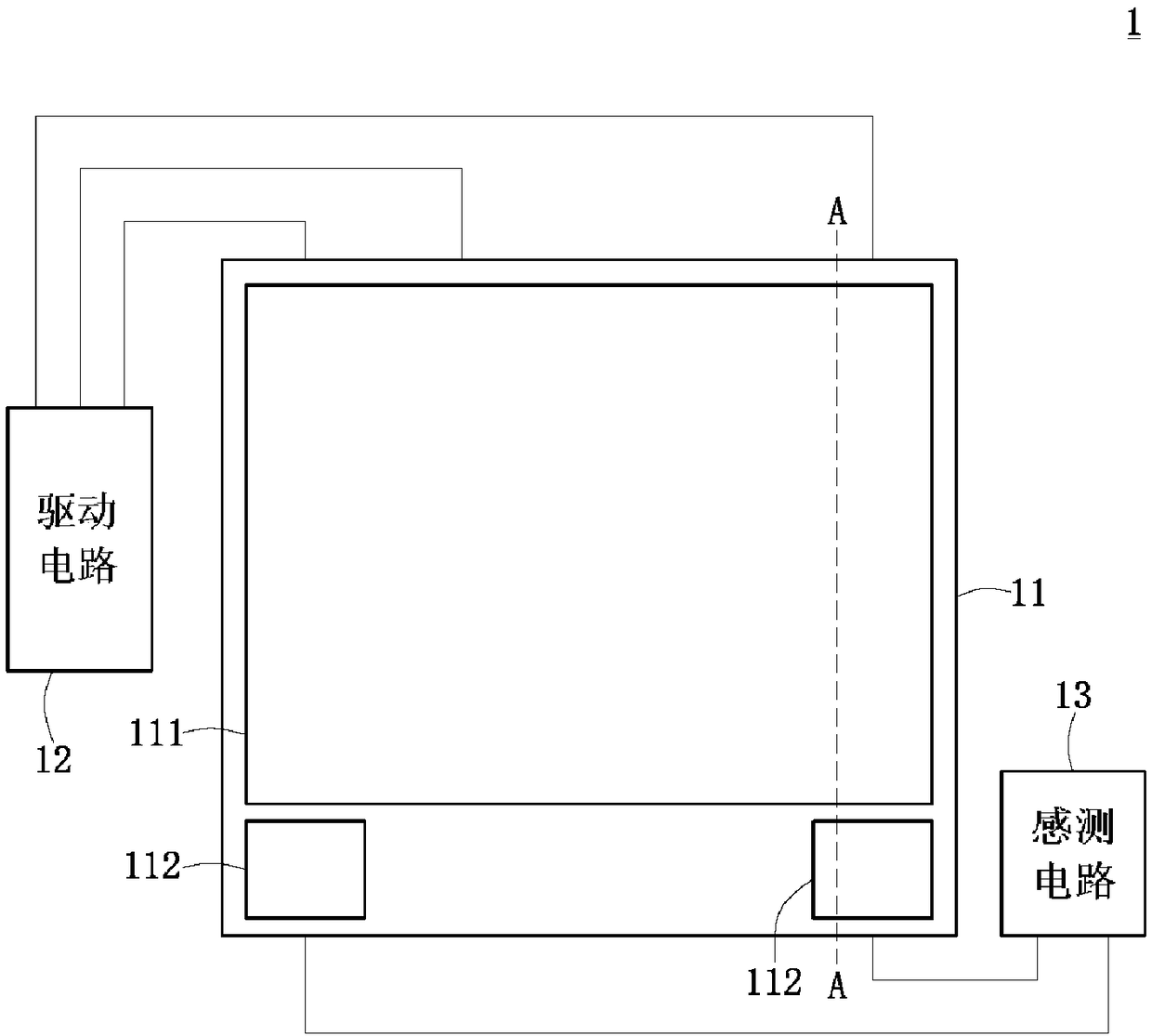
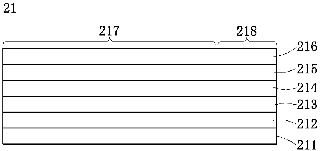
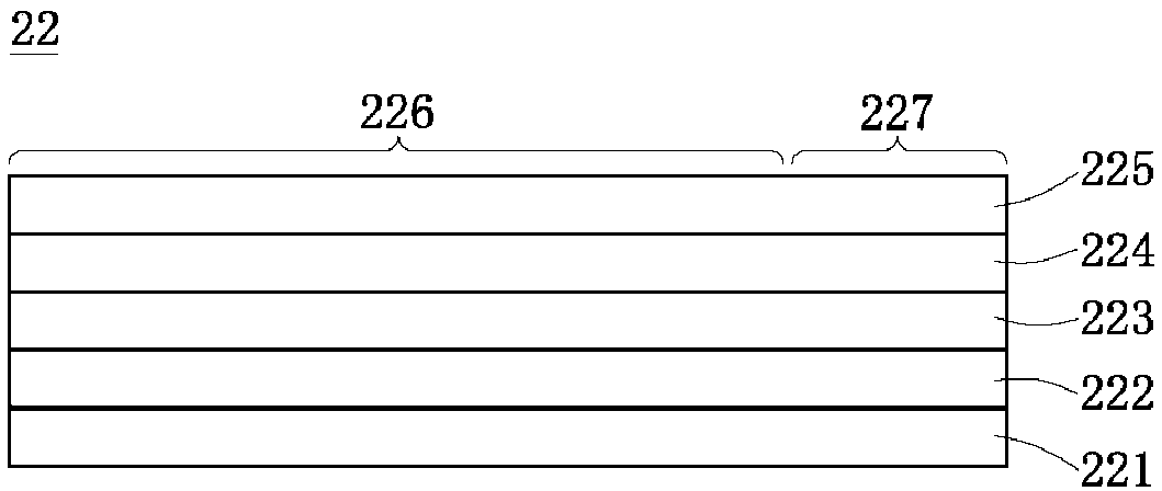
[0037] Embodiments of the present disclosure provide a liquid crystal display panel with an operation sensing function and a display device thereof. The liquid crystal display panel configu...


PUM


Abstract

The invention provides a liquid crystal display panel with an operation sensing function and a display device thereof. The liquid crystal display panel includes a display area and at least one operation sensing area not used for display. The operation sensing area includes at least one first electrode and at least one second electrode, wherein the first electrode of the operation sensing area doesnot receive pixel voltages, and the second electrode of the operation sensing area does not receive common voltages, so that the first electrode and / or the second electrode of the operation sensing area are used for sensing a sensing signal generated when a touch object touches or approaches the operation sensing area. According to the liquid crystal display panel, a touch control key function can be provided for the liquid crystal panel by only changing wiring layout, and an additional transparent touch control electrode layer does not need to be attached on an insulating substrate so that the yield of manufacture procedures of the touch control liquid crystal display panel can be improved, and manufacturing costs can be reduced.

Description

technical field [0001] The present disclosure relates to the field of display technology, and in particular, relates to a liquid crystal display panel and a display device thereof which do not need to additionally design a transparent touch electrode layer on an insulating substrate but have an operation sensing function. Background technique [0002] At present, liquid crystal display devices with touch function generally bond the liquid crystal display panel and the touch panel to form a touch display panel, wherein the touch panel has a transparent insulating substrate (for example, a plastic film or a glass substrate) and At least one touch electrode layer (for example, an ITO layer) plated on the insulating substrate. [0003] Since at least one additional touch electrode layer is required to sense the touch signal, and an additional insulating substrate is required to be bonded to the liquid crystal display panel, the above-mentioned touch display panel has advantages ...

Claims


Application Information

Patent Timeline
IPC IPC(8): G02F1/1333G02F1/1343G06F3/041
CPCG02F1/13338G02F1/134309G06F3/041
Inventor 吴上玄陈宏宾
Owner TENX (SHENZHEN) TECH LTD
Learn More