Permanent-magnet motor

A permanent magnet motor, permanent magnet technology, applied in synchronous motors with stationary armatures and rotating magnets, magnetic circuits, electric components, etc., can solve problems such as regular maintenance, heavy equipment, and low transmission efficiency

Pending Publication Date: 2018-05-29
SOUTH UNIVERSITY OF SCIENCE AND TECHNOLOGY OF CHINA
View PDF0 Cites 11 Cited by
  • Summary
  • Abstract
  • Description
  • Claims
  • Application Information

AI Technical Summary

Problems solved by technology

The existence of reduction gearbox or belt reduction device will inevitably bring many troubles, such as: low transmission efficiency, bulky, heavy equipment, noise pollution, need for lubrication, need for regular maintenance, etc.

Method used


Image

  • Permanent-magnet motor
  • Permanent-magnet motor
  • Permanent-magnet motor

Examples


Embodiment Construction

[0044] The present invention will be further described in detail below in conjunction with the accompanying drawings and embodiments. It should be understood that the specific embodiments described here are only used to explain the present invention, but not to limit the present invention. In addition, it should be noted that, for the convenience of description, only some structures related to the present invention are shown in the drawings but not all structures.

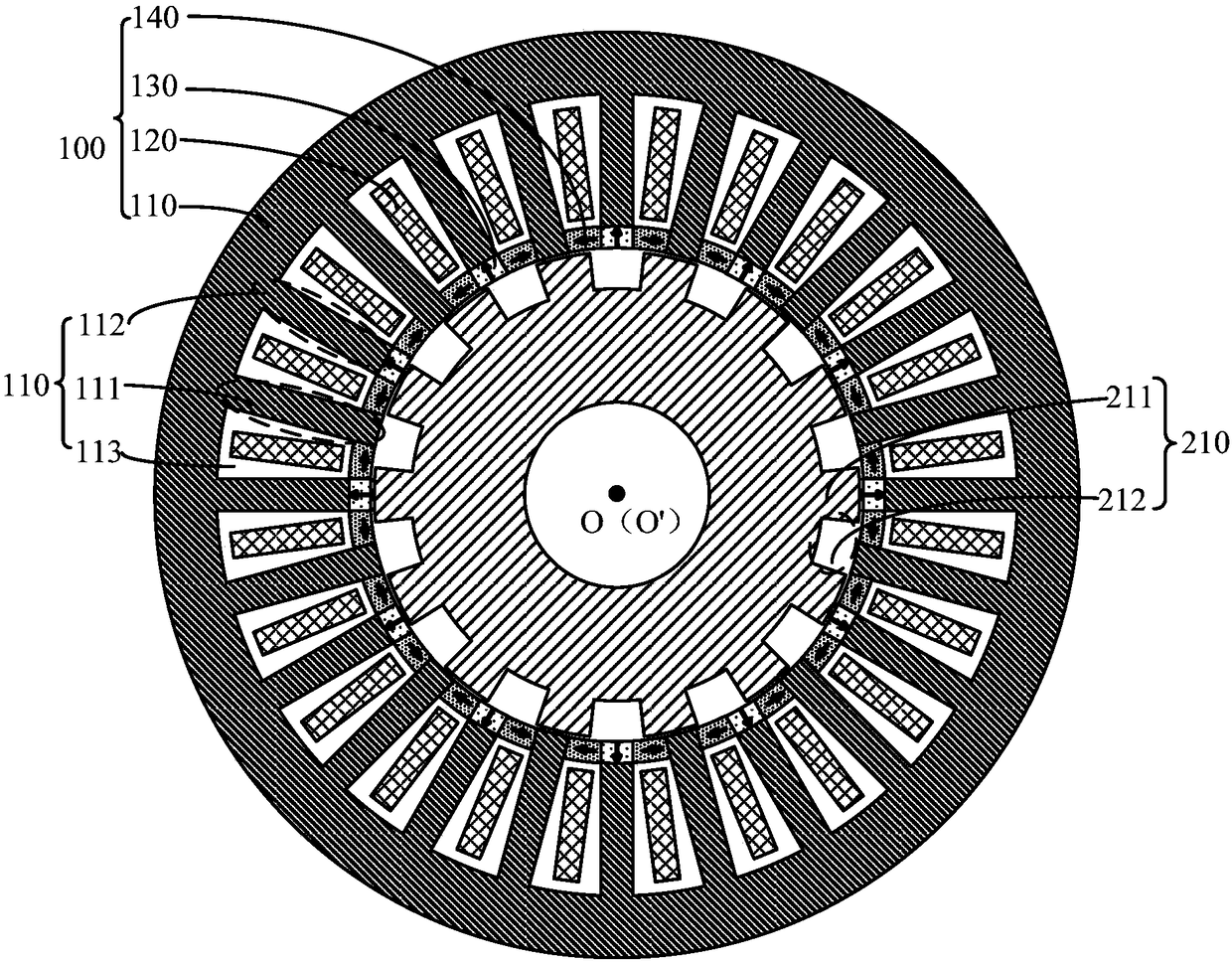
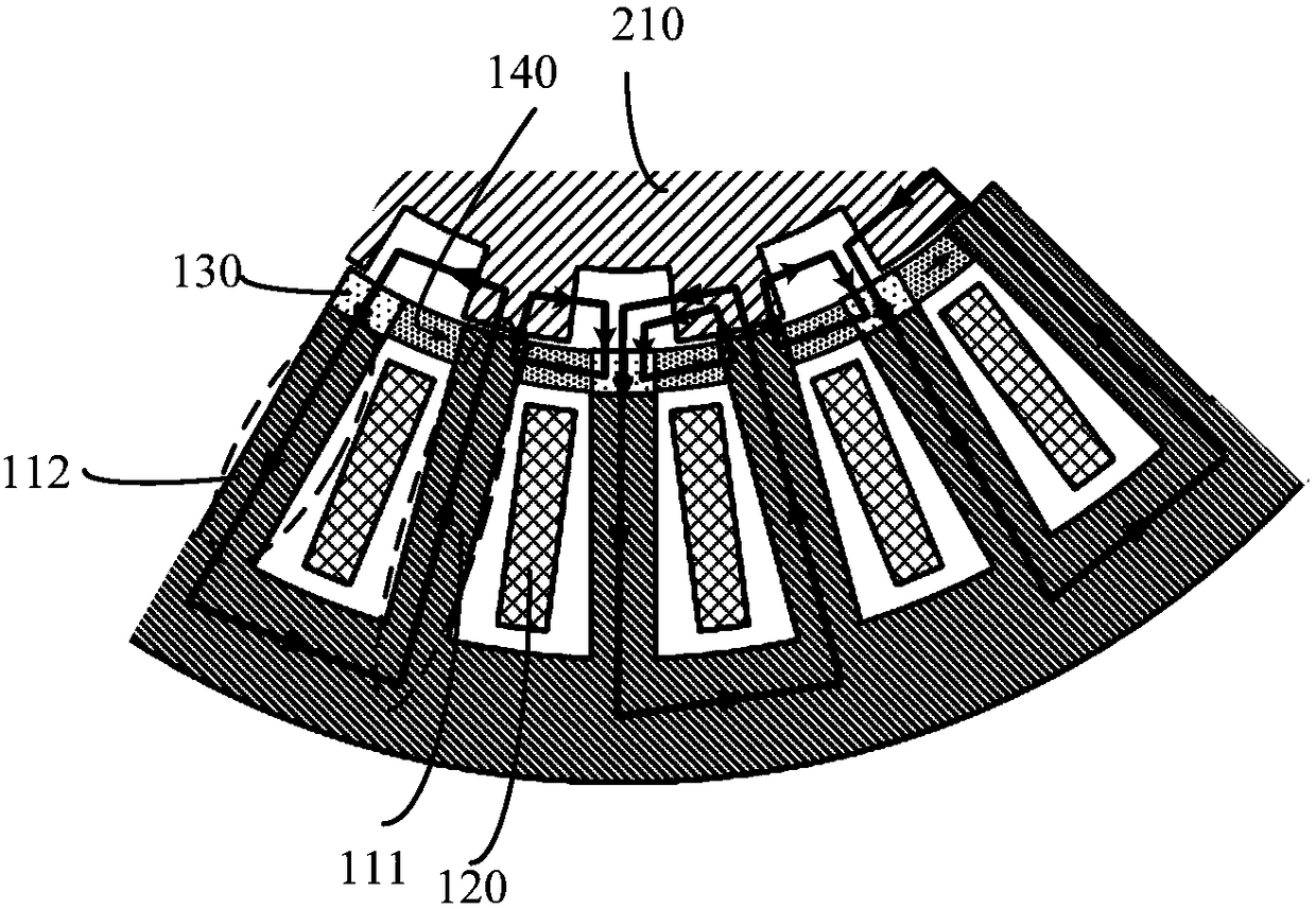
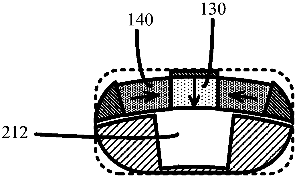
[0045] An embodiment of the present invention provides a permanent magnet motor. figure 1 It is a schematic cross-sectional structure diagram of a permanent magnet motor along a direction perpendicular to the axial direction provided by an embodiment of the present invention. The permanent magnet motor can be used in wind power generation, industrial robots, precision machine tools, oil field pumping systems, ship propulsion and other occasions. Such as figure 1 As shown, the permanent magnet motor includes an a...


PUM


Abstract

The embodiment of the invention discloses a permanent-magnet motor. The permanent-magnet motor comprises an annular stator structure and an annular rotor structure, wherein a stator core is provided with a plurality of stator modulation teeth, armature teeth and armature slots on an annular surface close to the rotor structure along the circumferential direction; the plurality of stator modulationteeth, armature teeth and armature slots are circularly arranged according to the order of one stator modulation tooth, one armature slot, one armature tooth and another armature slot; a first statorpermanent magnet corresponds to each armature tooth and is located at one end, close to the rotor structure, of the corresponding armature tooth; the first stator permanent magnets are magnetized along the radial direction; second stator permanent magnets are located in notches of the corresponding armature slots; the second stator permanent magnets are magnetized along the circumferential direction; and the second stator permanent magnets corresponding to two adjacent armature slots are opposite in magnetization direction; and a rotor core is alternately provided with a plurality of rotor teeth and rotor slots on the annular surface close to the stator structure along the circumferential direction. The permanent-magnet motor disclosed by the embodiment of the invention is capable of directly driving load to get rid of an intermediate transmission device in a traditional transmission system.

Description

technical field [0001] The invention relates to the field of motor manufacturing, in particular to a permanent magnet motor. Background technique [0002] The traditional low-speed transmission system is realized by using a high-speed motor with a reduction gearbox or a belt reduction device. The existence of reduction gearbox or belt reduction device will inevitably bring many troubles, such as: low transmission efficiency, bulky, heavy equipment, noise pollution, need for lubrication, need for regular maintenance, etc. [0003] Therefore, it is necessary to manufacture a direct drive motor to directly drive the load, so as to get rid of the intermediate transmission device in the traditional transmission system and eliminate all kinds of troubles caused by the intermediate transmission device. Contents of the invention [0004] An embodiment of the present invention provides a permanent magnet motor that can directly drive a load, so as to get rid of the intermediate tr...

Claims


Application Information

Patent Timeline
Patent Type & Authority Applications(China)
IPC IPC(8): H02K21/16H02K1/26H02K1/17H02K1/27
CPCH02K21/16H02K1/17H02K1/265H02K1/278H02K2213/03
Inventor 蹇林旎石玉君尉进邓正兴
Owner SOUTH UNIVERSITY OF SCIENCE AND TECHNOLOGY OF CHINA
Why Eureka
Try Eureka