System and method for optical coupling image acquisition time calibration

An image acquisition and optical coupling technology, applied in the field of image acquisition, can solve the problems of influence, the light source cannot be installed, and cannot work normally, and achieves the effects of high measurement accuracy, no damage to measurement, and avoidance of dislocation

Active Publication Date: 2018-05-29
BEIJING INSTITUTE OF TECHNOLOGYGY
View PDF5 Cites 6 Cited by
  • Summary
  • Abstract
  • Description
  • Claims
  • Application Information

AI Technical Summary

Problems solved by technology

[0011] The acquisition of images, especially the image acquisition of photomechanics, often involves the detection environment of high temperature, high wind speed, and high humidity. The light source

Method used


Image

  • System and method for optical coupling image acquisition time calibration
  • System and method for optical coupling image acquisition time calibration
  • System and method for optical coupling image acquisition time calibration

Examples


Embodiment 1

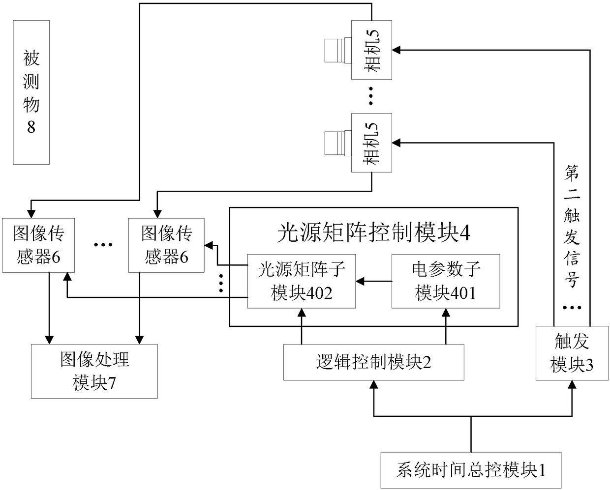
[0072] figure 1 It is a system diagram of the optical coupling image acquisition time calibration in Embodiment 1 of the present invention. See figure 1 , the system consists of:

[0073] The system time master control module 1 is respectively coupled with the logic control module 2 and the trigger module 3 to provide a reference time for the logic control module 2 and the trigger module 3 .

[0074] The logic control module 2 receives a reference time, and generates an electrical parameter control signal and a period control signal based on the reference time.

[0075] The temporal light generation module 3 includes a light source matrix sub-module 402 and an electrical parameter sub-module 401, the light source matrix sub-module 402 and the electrical parameter sub-module 401 are coupled, wherein the light source matrix sub-module 401 includes at least one light emitting unit.

[0076] The electrical parameter sub-module 401 is coupled with the logic control module 2, rec...

Embodiment 2

[0101] Utilizing the optical coupling type image acquisition time calibration system provided by the present invention, this embodiment provides an optical coupling type image acquisition time calibration method, Figure 4 For the flow chart of the method for calibrating the time of optically coupled image acquisition in Embodiment 2 of the present invention, please refer to Figure 4 , the method includes:

[0102] Step S101: system installation and setting steps: including:

[0103] According to the test requirements, set the relative position of the object under test and the camera, couple the system time master control module with the logic control module and the trigger module respectively, couple the quick search trigger module with the camera, and connect the camera with the image sensor Coupling, coupling the image sensor with the image processing module;

[0104] The logic control module is coupled with the time light generation module, the time light generation mod...

Embodiment 3

[0129] Using the optically coupled image acquisition time calibration system provided by the present invention, and on the basis of the optically coupled image acquisition time calibration method provided by the present invention, this embodiment provides a method for accurately measuring the distance between two or more cameras. The time difference method between startups, Figure 5 For the flow chart of precise positioning camera startup time difference in Embodiment 3 of the present invention, please refer to Figure 5 , the method includes:

[0130] Step S201: System installation steps

[0131] According to the test requirements, set the relative position of the object under test and the camera, couple the system time master control module with the logic control module and the trigger module respectively, couple the quick search trigger module with the camera, and connect the camera with the image sensor Coupling, the image sensor is coupled with the image processing mod...


PUM


Abstract

The invention provides a system and method for optical coupling image acquisition time calibration. The system for optical coupling image acquisition time calibration comprises a system time master control module, a logic control module, a time light generating module, a trigger module, a camera, an image sensor and an image processing module; wherein the system time master control module providesa reference time for the logic control module and the trigger module; the logic control module generates an electrical parameter control signal and a periodic control signal based on the reference time; the time light generating module comprises a light source matrix sub-module and an electrical parameter sub-module; the trigger module generates a trigger signal based on the reference time; the camera forms an optical path, and generates an acquisition control signal after the camera is triggered by the trigger signal; the image sensor is triggered by the acquisition control signal to receivethe optical matrix information and the reflected light of a measured object, so as to obtain a first image; and the image processing module converts the optical matrix information to the image acquisition time information to obtain a second image, wherein the second image is the first image marked the time information. By means of the system and method for optical coupling image acquisition timecalibration, the time that the camera shoots the image can be accurately located in extreme environments.

Description

technical field [0001] The invention belongs to the technical field of image acquisition, and in particular relates to a system and method for calibrating an optical coupling type image acquisition time. Background technique [0002] The camera is a commonly used image acquisition device in the fields of industrial production and scientific research. It is often used to photograph the dynamic process of objects, and obtain some qualitative or quantitative measurement results by analyzing the collected images. In photomechanical experiments, image processing algorithms are often used to quantitatively analyze images collected by industrial cameras to obtain mechanical quantities such as stress, strain, and displacement of the measured object. [0003] In many applications, two or more cameras need to work together to achieve dynamic measurement of objects in three-dimensional space or stitching measurement of a large field of view. In these applications, in order to obtain a...

Claims


Application Information

Patent Timeline
IPC IPC(8): H04N5/232G04F13/00
CPCG04F13/00H04N23/64
Inventor 刘振宇马沁巍田强马少鹏朱少青乔志正
Owner BEIJING INSTITUTE OF TECHNOLOGYGY
Why Eureka
Try Eureka