Adjustable straw processor

A processing machine and adjustable technology, which is applied to harvesters, agricultural machinery and implements, shovels, etc., can solve problems such as aggravation, hardening and airtightness, and increase of soil germs, so as to achieve convenient use, increase soil fertility, and good results.

Inactive Publication Date: 2018-06-01
霍邱县夏时农机制造有限公司
View PDF7 Cites 6 Cited by
  • Summary
  • Abstract
  • Description
  • Claims
  • Application Information

AI Technical Summary

Problems solved by technology

[0002] Straw returning to the field can increase soil organic matter, improve soil structure, loosen the soil, increase porosity, reduce capacity, and promote microbial activity and the growth of crop roots. However, if the method is improper, it will also lead to the increase of soil pathogens, the aggravation of crop diseases and the lack of seedlings (stiff seedlings) and other undesirable phenomena
Therefore, only by taking reasonable measures to return straw to the field can a good effect be achieved. For many years, the remaining straw after harvesting corn and other crops has been burned in large quantities, which has caused great pollution to the natural environment. On the other hand, due to the perennial pursuit of food High-yielding, continuously increasing crop density, thereby plundering the nutrients in the soil, making the soil extremely deficient in nutrients, compacted and airtight, and the bottom of the plow layer thickening year by year, causing crops to fall easily, and the situation of yield reduction is becoming increasingly severe. The straw processing machine is inconvenient to use, the straw is not completely crushed, and the straw is covered on the soil surface after crushing, and the effect of returning to the field is not ideal

Method used


Image

  • Adjustable straw processor
  • Adjustable straw processor
  • Adjustable straw processor

Examples


Embodiment Construction

[0019] The following will clearly and completely describe the technical solutions in the embodiments of the present invention with reference to the accompanying drawings in the embodiments of the present invention. Obviously, the described embodiments are only some, not all, embodiments of the present invention. Based on the embodiments of the present invention, all other embodiments obtained by persons of ordinary skill in the art without making creative efforts belong to the protection scope of the present invention.

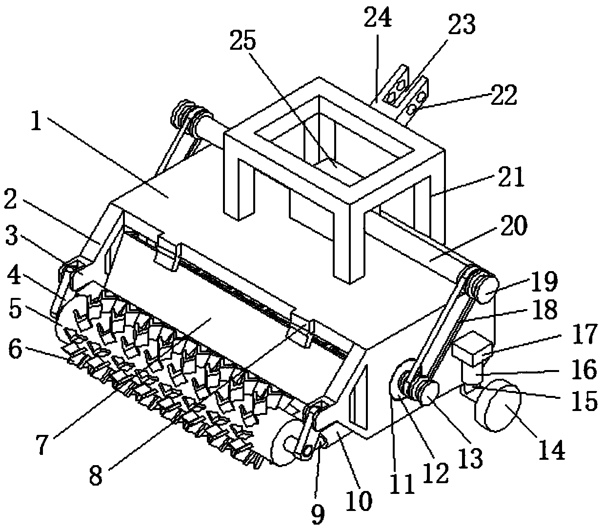
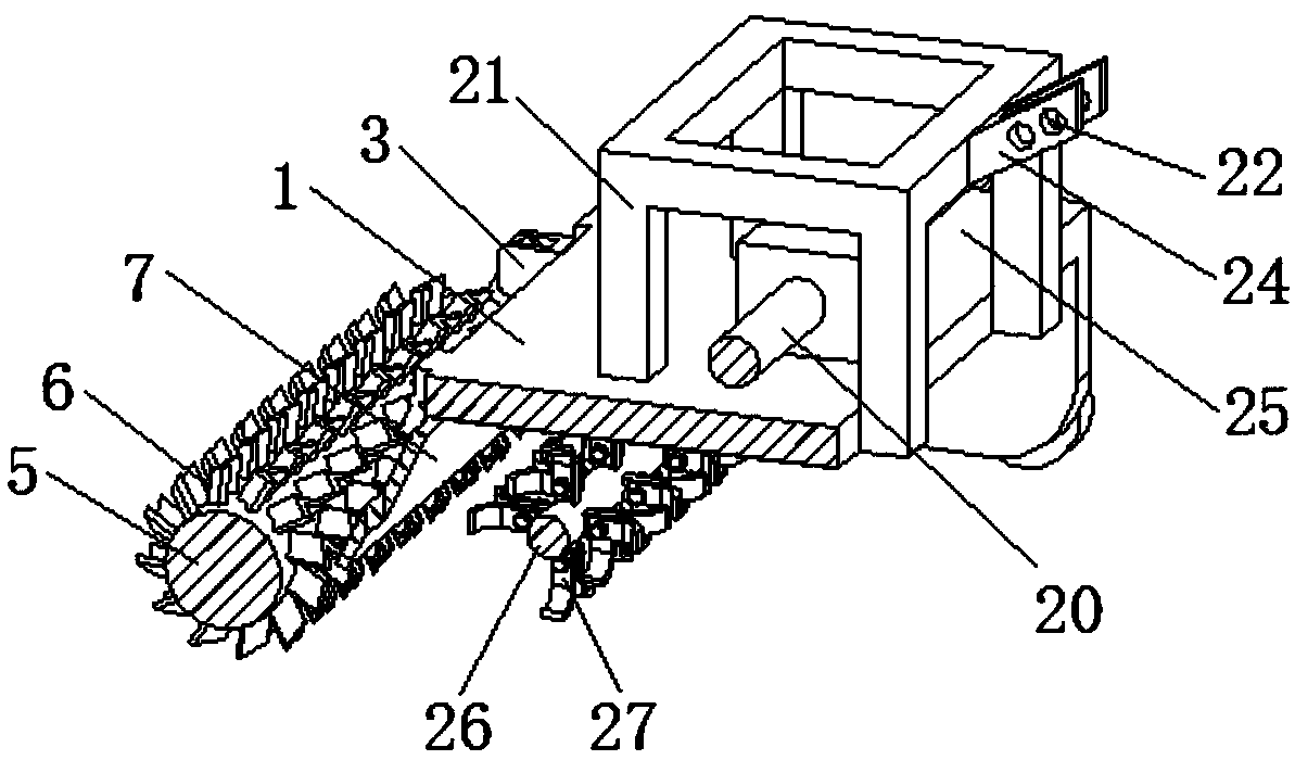
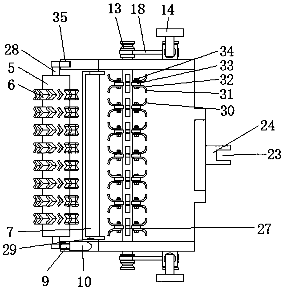
[0020] see Figure 1-3 , the present invention provides a technical solution: an adjustable straw processing machine, including a mounting frame 1, the mounting frame 1 is a U-shaped frame plate, a speed reducer 25 is provided on one side of the upper surface of the mounting frame 1, and the speed reducer 25 is connected to the external The transmission equipment is connected, the surface of both sides of the reducer 25 is connected with the transmission shaft...


PUM


Abstract

The invention discloses an adjustable straw processor. The processor comprises a mounting frame, a decelerator is arranged on one side of the upper surface of the mounting frame, the decelerator is connected with an external transmission device, surfaces of both sides of the decelerator are respectively connected with transmission shafts, first belt pulleys are arranged on one ends of the transmission shafts, grooves are respectively formed in the middle of the two ends of the mounting frame, bearings are clamped in the grooves, first rotating shafts are sleeved with the two bearings, and crushing mechanisms are evenly distributed on the outer surfaces of the first rotating shafts, two ends of the first rotating shafts are provided with second belt pulleys, the second belt pulleys are connected with the first belt pulleys through belts, the upper surface of the mounting frame is provided with a connecting frame, a traction mechanism is arranged on the side surface of the connecting frame, both sides of the left end of the mounting frame are respectively provided with fixing frames, and connecting blocks are arranged on the side surfaces of the fixing frames. The adjustable straw processor is convenient to use, and capable of quickly cutting and crushing straw and burying straw fragments in soil layers, straw turnover effects are good, and the depths of the soil layers where thestraw fragments are buried can be adjusted.

Description

technical field [0001] The invention relates to the technical field of agricultural machinery, in particular to an adjustable straw processing machine. Background technique [0002] Straw returning to the field can increase soil organic matter, improve soil structure, loosen the soil, increase porosity, reduce capacity, and promote microbial activity and the growth of crop roots. However, if the method is improper, it will also lead to the increase of soil pathogens, the aggravation of crop diseases and the lack of seedlings (stiff seedlings) and other undesirable phenomena. Therefore, only by taking reasonable measures to return straw to the field can a good effect be achieved. For many years, the remaining straw after harvesting corn and other crops has been burned in large quantities, which has caused great pollution to the natural environment. On the other hand, due to the perennial pursuit of food High-yielding, continuously increasing crop density, thereby plundering ...

Claims


Application Information

Patent Timeline
Patent Type & Authority Applications(China)
IPC IPC(8): A01B49/04A01D43/12
CPCA01B49/04A01D43/12
Inventor 时配江
Owner 霍邱县夏时农机制造有限公司
Why Eureka
Try Eureka