Liquid metal pouring technology capable of increasing hot metal flow rate and reducing pouring time
A technology of liquid metal and pouring time, which is applied in the direction of metal processing equipment, the control of molten metal pouring from the ladle, and the equipment for sending molten metal into the mold, etc., to achieve the effect of shortening the pouring time and speeding up the flow rate
- Summary
- Abstract
- Description
- Claims
- Application Information
AI Technical Summary
Problems solved by technology
Method used
Image

Examples
Embodiment 1
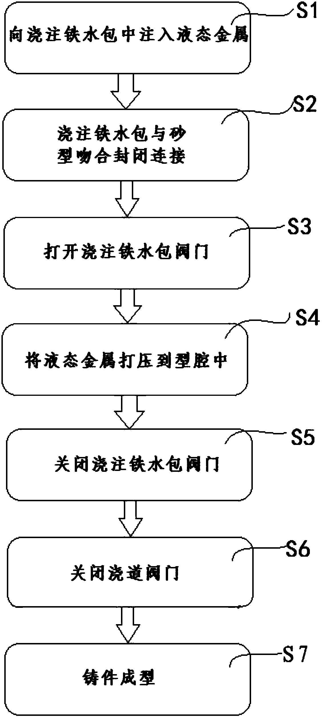
[0030] In the actual process, when vertical sand molds are poured in series, liquid metal is first injected into the pouring ladle, and the liquid metal is injected into the pouring ladle at a certain height from the sand mold. The series connection of the road and the sand mold realizes the connection between the sand mold and the pouring ladle. The pouring ladle is set higher than the height of the sand mold to ensure a certain height difference between the two, so that the liquid metal forms a certain pressure when pouring through the pouring ladle to speed up the flow rate. After the liquid metal is injected into the pouring ladle, the liquid metal must be pressed into the cavity in the sand mold through the pouring ladle through the runner. The most central sand mold is connected in series with the sand mold of vertical molding by pouring ladle. The liquid metal is directly pressed into each vertical sand mold by pouring the ladle to complete the pouring process of the c...
Embodiment 2
[0033]In the actual process, when vertical sand molds are poured in series, liquid metal is first injected into the pouring ladle, and the liquid metal is injected into the pouring ladle at a certain height from the sand mold. The series connection of the road and the sand mold realizes the connection between the sand mold and the pouring ladle. The pouring ladle is set higher than the height of the sand mold to ensure a certain height difference between the two, so that the liquid metal forms a certain pressure when pouring through the pouring ladle to speed up the flow rate. After the liquid metal is injected into the pouring ladle, the liquid metal in the pouring ladle must be pressed into the sand mold, and the liquid metal is pressed into the cavity through the runner. The sprue is lengthened on the water riser at the upper part of the vertically molded sand mold, and the water riser is arranged on the upper part of the sprue, and the lower part of the extended sprue is m...
Embodiment 3
[0035] In the actual process, when vertical sand molds are poured in series, liquid metal is first injected into the pouring ladle, and the liquid metal is injected into the pouring ladle at a certain height from the sand mold. The series connection of the road and the sand mold realizes the connection between the sand mold and the pouring ladle. The pouring ladle is set higher than the height of the sand mold to ensure a certain height difference between the two, so that the liquid metal forms a certain pressure when pouring through the pouring ladle to speed up the flow rate. After the liquid metal is injected into the ladle, the water outlet at the lower part of the valve of the ladle is directly connected to the longitudinal sprue at the lower part of the vertical sand mold. The longitudinal sprue anastomotic connection device for pouring the lower part of the ladle is made separately. The liquid metal is directly pressed into each vertical sand mold through the longitudi...
PUM
 Abstract
Description
Claims
Application Information
 - Generate Ideas
- Intellectual Property
- Life Sciences
- Materials
- Tech Scout
- Unparalleled Data Quality
- Higher Quality Content
- 60% Fewer Hallucinations
Browse by: Latest US Patents, China's latest patents, Technical Efficacy Thesaurus, Application Domain, Technology Topic, Popular Technical Reports.
© 2025 PatSnap. All rights reserved.Legal|Privacy policy|Modern Slavery Act Transparency Statement|Sitemap|About US| Contact US: help@patsnap.com