
False tooth polishing machine

A technique for polishing machines and dentures, which is applied in the field of denture polishing machines, and can solve problems such as poor precision, damaged dentures, and uneven manual polishing

Pending Publication Date: 2018-06-01
吉林百合口腔医院股份有限公司
View PDF16 Cites 5 Cited by
  • Summary
  • Abstract
  • Description
  • Claims
  • Application Information

AI Technical Summary

Problems solved by technology

[0005] The purpose of the present invention is to provide a denture polishing machine to solve the problems of uneven manual polishing, poor precision, and damage to dentures by conventional fixture fixing methods

Method used


Image

  • False tooth polishing machine
  • False tooth polishing machine
  • False tooth polishing machine

Examples


Embodiment 1

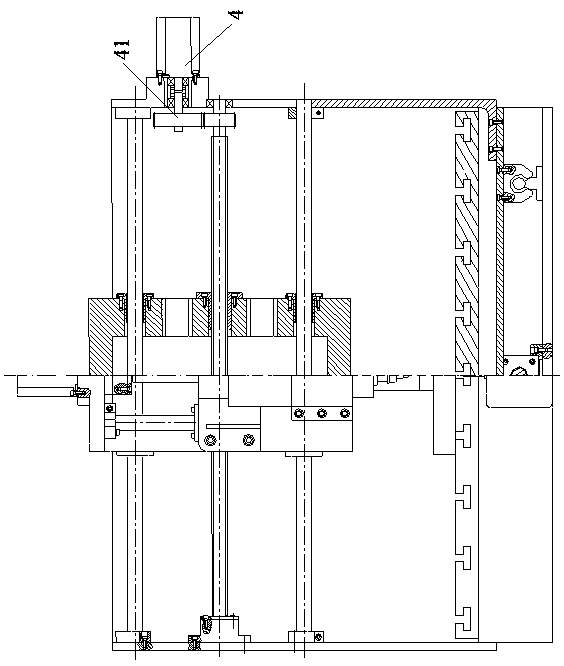
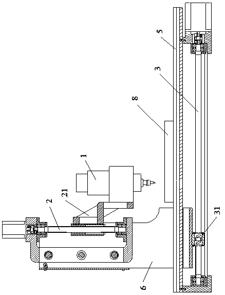
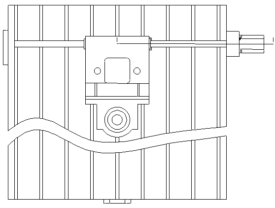
[0021] See Figure 1-8 , a kind of denture polishing machine, it comprises: vertical feeding mechanism 2, lateral feeding mechanism 3, longitudinal feeding mechanism 4, workbench 5, fixture 8;

[0022] Vertical feeding mechanism 2, which includes: servo motor, shaft coupling, bearing, lead screw, screw nut, screw nut seat, bent plate 21 connected with the screw nut seat, bent plate 21 is connected with polishing head 1; The feeding mechanism 2 is fixed on the support 6, and the lower end of the support 6 is connected with the transverse feed mechanism 3;

[0023] The transverse feed mechanism 3 includes: a servo motor, a shaft coupling, a bearing, and a screw nut clearance elimination structure 31; the screw nut clearance elimination structure 31 includes; a lead screw 311, a left Side outer ring gear 312, left inner ring gear 313, screw female seat 314, screw nut 315, right inner ring gear 316, right outer ring gear 317, left outer ring gear 312 meshes with left inner ring g...

Embodiment 2

[0027] Preferably, in order to further improve the accuracy of the vertical feed mechanism 2, the lateral feed mechanism 3, and the longitudinal feed mechanism 4, the screw nut gap elimination structure 31 is adopted in these three feed mechanisms, and the tooth side gap elimination active The gear 41 and the driven gear meshed with it can realize the low-speed, constant-speed and high-speed feed motion of the feed mechanism by adjusting the transmission ratio of the active gear 41 and the driven gear meshed with it to eliminate backlash.

[0028] When assembling and adjusting, the arc-shaped hooks at both ends of the tension spring 416 are respectively hung on the middle round holes of the flat heads of the long screw 415 and the short screw 417 to ensure that after the gear clearance mechanism is installed, the thin-toothed gear 411 on the right 1. The tooth groove of the thin-toothed gear 412 on the left side at the same position, the tooth profile curved surface of each gea...


PUM


Abstract

The invention discloses a false tooth polishing machine which comprises a polishing head, a vertical feed mechanism, a transverse feed mechanism, a longitudinal feed mechanism, a workbench and a clamp. The polishing head is fixed to the vertical feed mechanism through a bent plate. The vertical feed mechanism is fixed to the longitudinal feed mechanism. The longitudinal feed mechanism is fixed toa lathe bed. The workbench is arranged on the transverse feed mechanism, and the clamp is arranged on the workbench. The transverse feed mechanism comprises a servo motor, a coupling, a bearing and alead screw and nut clearance elimination structure. The longitudinal feed mechanism comprises a servo motor, a coupling, a bearing, a tooth backlash elimination driving gear, a driven gear, a lead screw and a nut. The clamp comprises a 24V direct current power source, a groove type clamp body, a magnetic coil and magnetorheological fluid. The polishing machine is uniform in polishing and high in polishing precision, and the clamp for fixing false teeth does not damage the false teeth.

Description

technical field [0001] The invention belongs to the technical field of denture processing, and in particular relates to a denture polishing machine. Background technique [0002] Dentures (or "dentures") are generally divided into: full dentures, fixed dentures, removable dentures and implant dentures. Among them, the complete denture is composed of dentures and denture bases. The dentures are used to restore the appearance of the natural dentition, the function of occlusion and auxiliary pronunciation. Upper and lower edentulous jaws. [0003] As an emerging technology in the field of rapid prototyping, 3D printing technology is attracting more and more attention in its application. In the field of oral denture production, it can realize the automatic production of denture production, with less consumables and low cost. It has changed the traditional production mode of dentures and has broad potential. Prospects. At present, Fused Deposition Modeling (Fused Deposition Mo...

Claims


Application Information

Patent Timeline
Patent Type & Authority Applications(China)
IPC IPC(8): B24B29/02B24B47/20B24B41/06B24B47/28A61C13/08
CPCA61C13/08B24B29/02B24B41/062B24B47/20B24B47/28
Inventor 董长安王丽娟周立林孙一飞孙长玲刘岩任军赵莉张晓雨刘春光纪翠翠董军武贾亚梅丛赫姜春子李跃恒杨旭崔艺兰赵立花刘笑笑辛影刘勇甘丽莉何旭张丽云杨长明李婷婷栾鸿雁李洪霞刘敏任秋颖徐凤孙百玲
Owner 吉林百合口腔医院股份有限公司
Learn More