Nut screwing device

A nut and anchor bolt technology, applied in screwdrivers, wrenches, wrenches, etc., to shorten the production cycle, reduce cost losses, and ensure safe use

Pending Publication Date: 2018-06-01
HARBIN DONGAN ENGINE GRP
View PDF0 Cites 1 Cited by
  • Summary
  • Abstract
  • Description
  • Claims
  • Application Information

AI Technical Summary

Problems solved by technology

[0003] The purpose of the present invention is to provide a nut tightening device, which is mainly aimed at the structure that large diameter nuts need a large torque to be tightened and disassembled

Method used


Image

  • Nut screwing device

Examples


Embodiment Construction

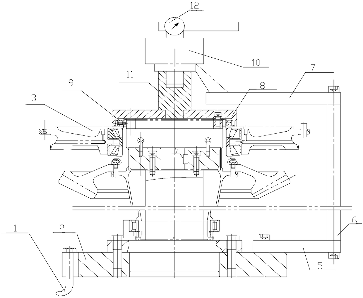
[0007] Such as figure 1 As shown, the nut tightening device includes a base 2, an anchor bolt 1, a positioning spline 13, a nut wrench 8, an adapter rod 11, a torque multiplier 10, a dial type torque wrench 12, a lower horizontal plate 5, a vertical plate 6, The anti-rotation plate 7, the base 2 are fixed on the ground by anchor bolts, and the part 3 is fixedly installed on the base 2, wherein the nut 9 to be dismantled is located at the top of the part 3, and the torque multiplier 10 is arranged on the upper part of the nut 9 to be dismantled, through the anti-rotation The rotating plate 7, the vertical plate 6, and the lower horizontal plate 5 are fixed on the base 2, the torque input end of the torque multiplier 10 is connected to the dial type torque wrench 12, and the torque output end is fixedly connected to the nut wrench 8 through the adapter rod 11. The nut wrench 8 cooperates with the nut 9 to be removed.


PUM


Abstract

The invention relates to a nut screwing device. The nut screwing device comprises a base, an anchor bolt, a nut wrench, a connecting rod, a torque multiplier and a dial type torque wrench, wherein the base 2 is fixed to the ground by virtue of the anchor bolt, a part is fixedly installed on the base, the torque multiplier is arranged just on the upper part of a to-be-disassembled nut and is fixedto the base by virtue of an anti-rotation plate, a vertical plate and a lower transverse plate, the moment input end of the torque multiplier is connected with the dial type torque wrench, the momentoutput end of the torque multiplier is fixedly connected with the nut wrench by virtue of the connecting rod, and the nut wrench is matched with the to-be-disassembled nut. According to the nut screwing device, the large-moment and large-diameter nut can be screwed and disassembled by adopting small moment and small space, the use safety is guaranteed, the unnecessary cost loss caused by repair or replacement of a new product is reduced, and the production cycle is shortened.

Description

technical field [0001] The invention relates to a tightening device, in particular to a nut tightening device with large torque and large diameter. Background technique [0002] In various industries in the industry, it is quite difficult to fasten and disassemble large-diameter, high-torque nuts, especially when it is difficult for personnel to construct and the work site is limited, it is even more difficult to use a large-size torque wrench, and sometimes it is even impossible. operational. For the tightening and dismounting of nuts with large diameter and high torque, the existing force boosting system generally uses a hydraulic cylinder structure to boost force to achieve high torque requirements. But this kind of structure is very inconvenient to operate. If it is often split and operated, it will bring a lot of workload to the operator, greatly reduce the work efficiency, and prolong the production cycle at the same time, resulting in unnecessary waste of resources. ...

Claims


Application Information

Patent Timeline
Patent Type & Authority Applications(China)
IPC IPC(8): B25B17/02B25B23/14
CPCB25B17/02B25B23/14
Inventor 王莹李野苏毅赵龙李晓东
Owner HARBIN DONGAN ENGINE GRP
Why Eureka
Try Eureka