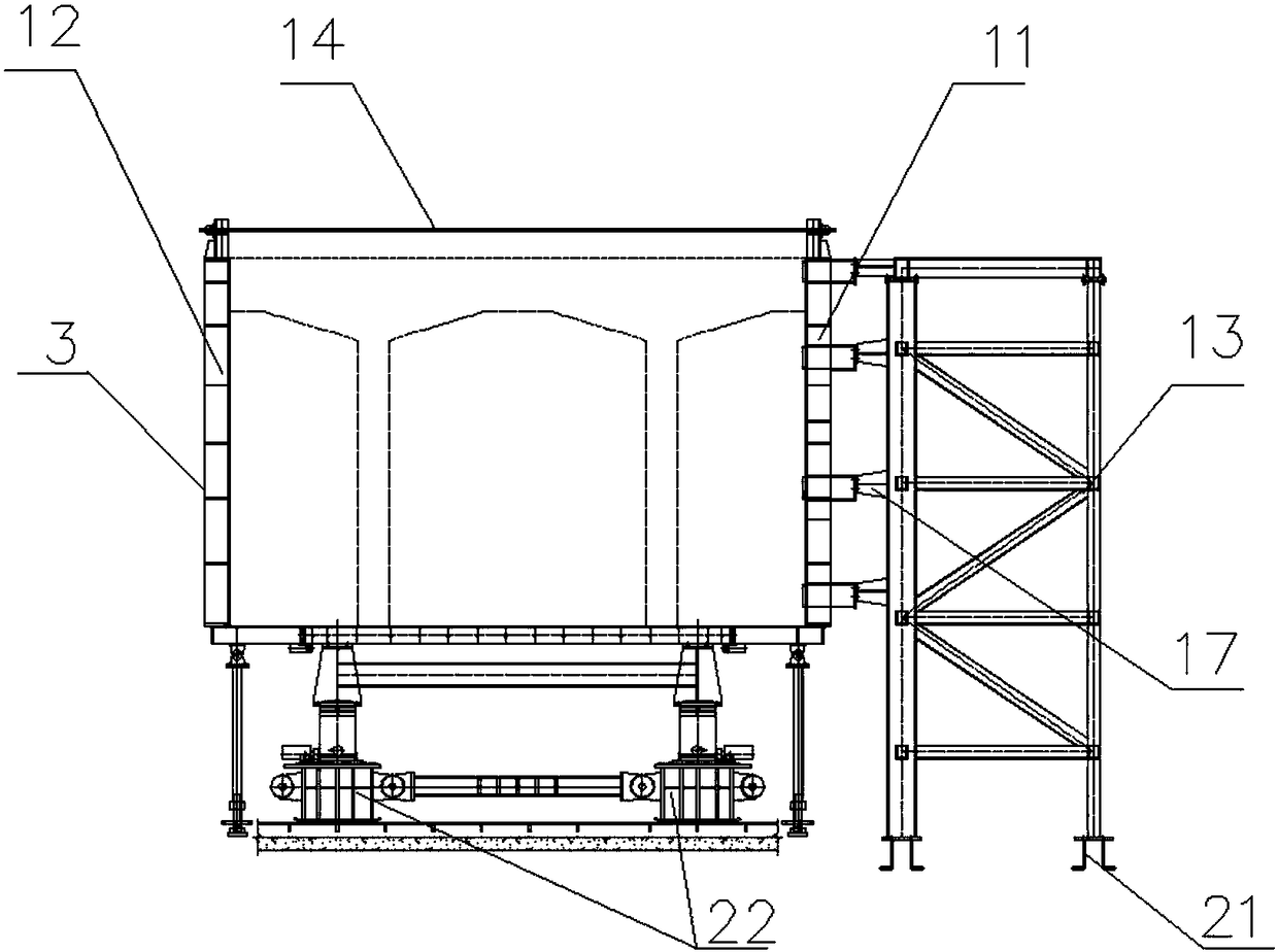
Prefabricated form for PK section concrete box beam segment

A technology for concrete box girders and formwork, which is applied in the direction of mold panels, molds, manufacturing tools, etc., can solve the problems of formwork assembly, disassembly, and low beam moving efficiency, and achieve the effects of shortening the construction period, ensuring structural quality, and increasing beam moving speed

Inactive Publication Date: 2018-06-01
CHINA RAILWAY CONSTR BRIDGE ENG BUREAU GRP +1
View PDF8 Cites 3 Cited by
  • Summary
  • Abstract
  • Description
  • Claims
  • Application Information

AI Technical Summary

Problems solved by technology

However, due to the characteristics of the PK section concrete box girder structure, the efficiency of formwork assembly, disassembly, and beam removal is low during the prefabrication construction process using the "short-line method" on the ground. At present, this technology is not yet mature in my country.

Method used


Image

  • Prefabricated form for PK section concrete box beam segment
  • Prefabricated form for PK section concrete box beam segment
  • Prefabricated form for PK section concrete box beam segment

Examples


Embodiment Construction

[0024] It should be noted that, in the case of no conflict, the embodiments of the present invention and the features in the embodiments can be combined with each other.

[0025] In describing the present invention, it should be understood that the terms "center", "longitudinal", "transverse", "upper", "lower", "front", "rear", "left", "right", The orientations or positional relationships indicated by "vertical", "horizontal", "top", "bottom", "inner", "outer", etc. are based on the orientation or positional relationships shown in the drawings, and are only for the convenience of describing the present invention Creation and simplification of description, rather than indicating or implying that the device or element referred to must have a specific orientation, be constructed and operate in a specific orientation, and therefore should not be construed as limiting the invention. In addition, the terms "first", "second", etc. are used for descriptive purposes only, and should no...


PUM


Abstract

The invention creates and provides a prefabricated form for a PK section concrete box beam segment. The prefabricated form comprises a side form assembly, a bottom form assembly, an end form assemblyand slippage assemblies, wherein the side form assembly comprises a side form bracket and a side form supported by the side form bracket; a movable form is arranged on the side form bracket; a hydraulic jack brace rod for bracing on the ground is arranged at the lower end of the side form bracket; the bottom form assembly comprises a bottom form supporting beam; a bottom form is arranged at the upper end of the bottom form supporting beam; a bottom form supporting rod is arranged at the lower end of the bottom form supporting beam; the end form assembly comprises a fixed end form and a movableend form which are correspondingly arranged at two ends of the box beam segment; each slipping assembly comprises a traveling bracket arranged at the lower end of the bottom form; and a slippery bootis arranged at the lower end of each traveling bracket. The slipping assemblies are arranged, so that the beam moving speed can be greatly increased; the prefabricated form is applicable to prefabricating the large-tonnage PK section concrete box beam segment by adopting a short line method, the production efficiency of a composite beam cable-stayed bridge is improved, the construction period isshortened, and the construction cost is beneficial for being reduced.

Description

technical field [0001] The invention belongs to the technical field of concrete beam prefabrication construction, and in particular relates to a segmental prefabricated template of a PK section concrete box girder. Background technique [0002] Most of the traditional PK section concrete box girders of cable-stayed bridges adopt the cast-in-place method of brackets, so the requirements for formwork technology are relatively simple. However, due to the characteristics of the PK section concrete box girder structure, the efficiency of formwork assembly, disassembly, and beam removal is low during the prefabrication process using the "short-line method" on the ground. At present, this technology is not yet mature in my country. How to adapt to the "short-line method" construction technology, save construction costs, and significantly improve the production efficiency of composite girder cable-stayed bridges on the premise of ensuring project quality is an urgent problem to be s...

Claims


Application Information

Patent Timeline
Patent Type & Authority Applications(China)
IPC IPC(8): B28B7/00
CPCB28B7/0002B28B7/0029B28B7/0055
Inventor 宋伟俊赵健龚国锋陈宁贤朱永盛田亮李春江于浩业杨占伟孙百锋刘春城姜延开岳超杰
Owner CHINA RAILWAY CONSTR BRIDGE ENG BUREAU GRP
Why Eureka
Try Eureka