[0019] In order to make the technical means, creative features, objectives and effects of the present invention easy to understand, the present invention will be further explained below in conjunction with specific embodiments.
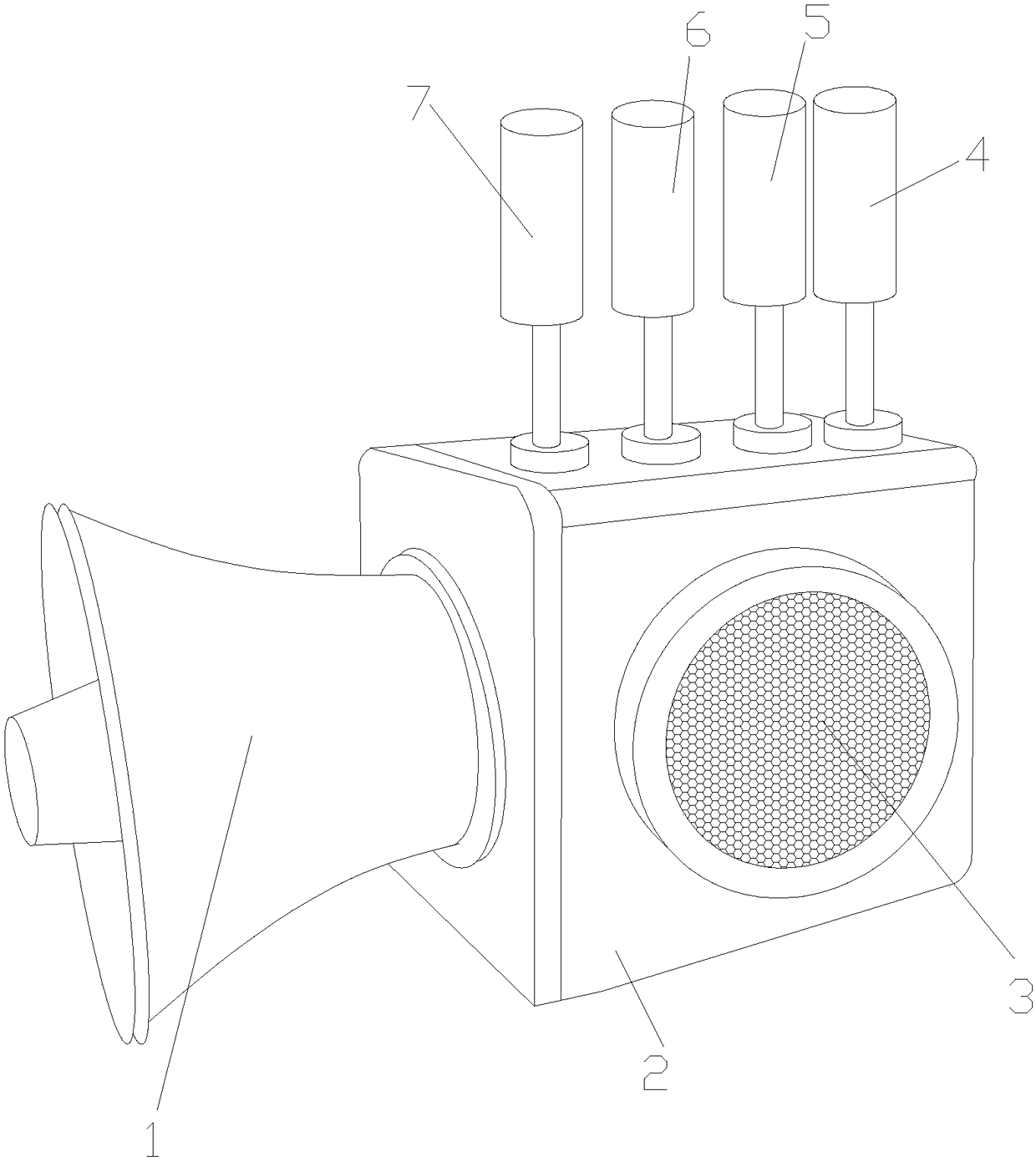
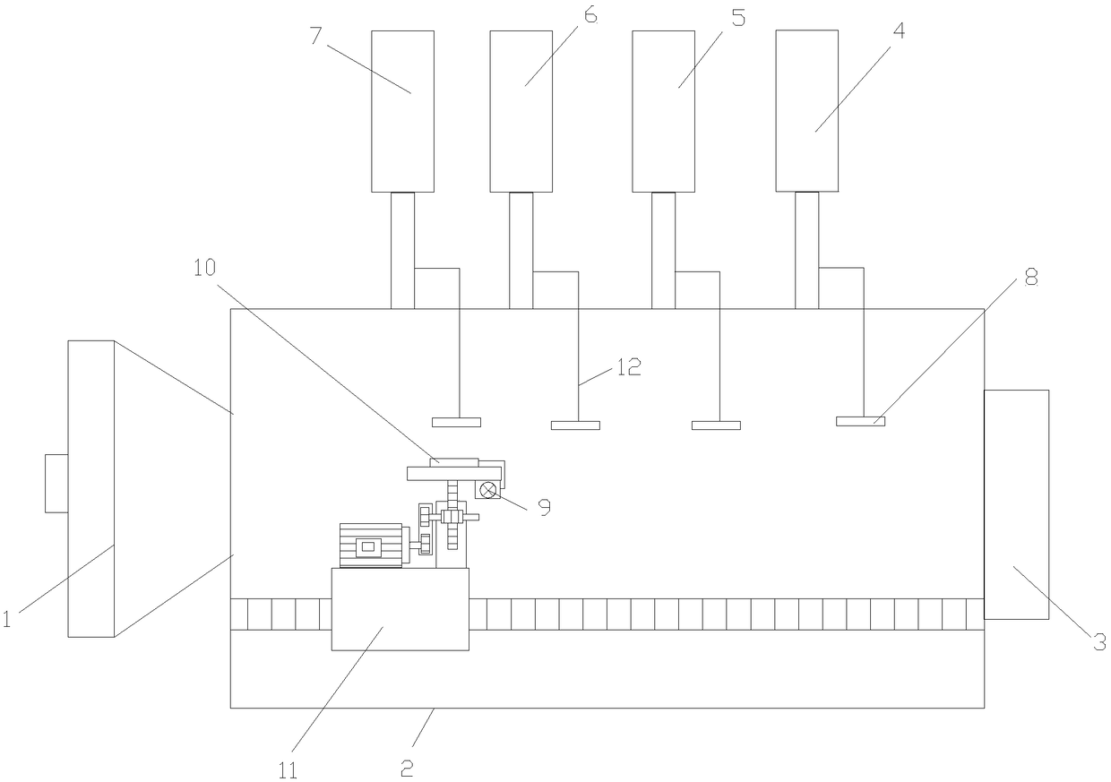
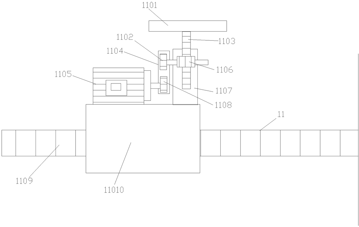
[0020] See Figure 1-Figure 3 , The present invention provides a technical solution for an early warning device for unmanned aerial vehicles: an early warning device for unmanned aerial vehicles, whose structure includes an early warning horn 1, an early warning device housing 2, a signal collector 3, and a speed alarm 4 , Height alarm 5, wind speed alarm 6, humidity alarm 7, power supply negative contact 8, power supply control box 9, power supply positive contact 10, signal alarm control mechanism 11, power connection line 12, the early warning horn 1 Connected to one end of the early warning device housing 2, a signal collector 3 is embedded on the front end surface of the early warning device housing 2, and the speed alarm 4 is connected to the other side of the upper end surface of the early warning device housing 2, One end of the speed alarm 4 is provided with a height alarm 5, the height alarm 5 is provided at the other end of the wind speed alarm 6, and one side of the upper end surface of the early warning device housing 2 is connected with a humidity alarm The other end of the humidity alarm 7 is provided with a wind speed alarm 6. The speed alarm 4, the altitude alarm 5, the wind speed alarm 6, and the humidity alarm 7 are all connected to the power supply through the power connection line 12 The negative contact 8 is connected. The negative power contact 8 is provided on the inner surface of the early warning device housing 2. The inner surface of the early warning device housing 2 is also provided with a signal alarm control mechanism 11, the signal alarm The upper surface of the control mechanism 11 is provided with a power positive contact 10, the power positive contact 10 and the power control box 9 are connected by a power connection line 12, the signal alarm control mechanism 11 is driven by a push plate 1101, a worm The gear 1102, the screw rod 1103, the transmission belt 1104, the drive motor 1105, the worm 1106, the telescopic holder 1107, the drive motor transmission gear 1108, the transmission slide bar 1109, and the slider 11010 are composed of the lower end surface of the push plate 1101 and the wire The rod 1103 is welded together, the lower end surface of the screw rod 1103 is longitudinally penetrated through the telescopic holder 1107, the worm 1106 is transversely penetrated through the telescopic holder 1107 and connected with the screw rod 1103, one end of the worm 1106 The worm transmission gear 1102 is connected by nested fit. The worm transmission gear 1102 is connected to the drive motor transmission gear 1108 through a transmission belt 1104. The drive motor transmission gear 1108 is connected to the drive motor by nested fit. At the other end of 1105, the drive motor 1105 is arranged on the upper surface of the slider 11010, the transmission slide bar 1109 is transversely penetrated through the slider 11010, and the upper surface of the push plate 1101 is provided with a positive power supply The contact 10, the early warning device housing 2 is a hollow rectangular structure, the negative power supply contacts 8 are provided with four parallel to each other, and the screw 1103 is a cylindrical structure with a length of 3-5 cm The shape of the slider 11010 is rectangular, the transmission sliding rod 1109 is a cylindrical structure with a length of 10-15 cm, and the material of the telescopic holder 1107 is alloy.
[0021] The signal collector-3 mentioned in this patent is a sensor that uses sensor technology to collect signals on the speed, height, wind speed and humidity of the surrounding environment.
[0022] When using this device, the user uses the signal collector 3 to collect the signal of the drone's speed, altitude and the wind speed and humidity of the surrounding environment. When the speed, height of the drone and any data of the wind speed and humidity of the surrounding environment exceed At the limit set by the device, the transmission slide bar 1109 drives the slider 11010 to rotate, so that the slider moves to the corresponding position of the negative power contact 8 that exceeds the limit set by the device. At the same time, the drive motor 1105 is controlled to rotate, and the drive motor 1105 drives the drive motor transmission gear 1108 to rotate, and the drive motor drive gear 1108 drives the worm transmission gear 1102 through the transmission belt 1104. The worm 1106 follows the worm transmission gear 1102 to rotate and drives the screw 1103 upwards. The screw 1103 drives the push plate 1101 during the ascent And the power supply positive contact 10 is lifted upwards, so that the power supply positive contact 10 contacts the corresponding power negative contact 8 that exceeds the limit set by the device, and the power is turned on. At this time, the corresponding alarm exceeds the limit set by the device. The device starts to alarm, so as to realize that the early warning device of the equipment used for the UAV can control the corresponding alarm according to the corresponding limit signal that exceeds the device setting when in use, so that the user can make corresponding adjustments to the UAV. , Easy to use, strong practicability.
[0023] The problem solved by the present invention is that the prior art cannot specifically remind the user of the problem of the drone during use, so that the user cannot make corresponding adjustments to the drone in time, which is inconvenient to use and poor in practicability. The present invention adopts It is equipped with a signal alarm control mechanism, which realizes that the early warning device of the equipment used for the UAV can control the corresponding alarm according to the corresponding signal exceeding the limit set by the equipment when in use, so that the user can make the corresponding response to the UAV. Adjustable, easy to use, and practical.
[0024] The above shows and describes the basic principles and main features of the present invention and the advantages of the present invention. For those skilled in the art, it is obvious that the present invention is not limited to the details of the above exemplary embodiments, and does not deviate from the spirit or basics of the present invention. In the case of features, the present invention can be implemented in other specific forms. Therefore, from any point of view, the embodiments should be regarded as exemplary and non-limiting. The scope of the present invention is defined by the appended claims rather than the foregoing description, and therefore it is intended to fall within the claims. All changes within the meaning and scope of equivalent elements of are included in the present invention. Any reference signs in the claims should not be regarded as limiting the claims involved.
[0025] In addition, it should be understood that although this specification is described in accordance with the implementation manners, not each implementation manner only includes an independent technical solution. This narration in the specification is only for clarity, and those skilled in the art should consider the specification as a whole The technical solutions in the embodiments can also be appropriately combined to form other implementations that can be understood by those skilled in the art.