Flap valve with buffer structures

A technology of buffer structure and buffer part, which is applied in the field of door flaps, can solve problems such as affecting normal use, cracking of concrete structures, deformation of flap door structures, etc., and achieves the effect of simple structure.

Inactive Publication Date: 2018-06-01
方芳
View PDF0 Cites 3 Cited by
  • Summary
  • Abstract
  • Description
  • Claims
  • Application Information

AI Technical Summary

Problems solved by technology

The current flap door generally has the problem of impact force during the closing process. Under frequent high-intensity impact, problems such as cracking of the concrete structure and deformation of the flap door structure will occur, which will affect normal use.

Method used


Image

  • Flap valve with buffer structures
  • Flap valve with buffer structures
  • Flap valve with buffer structures

Examples


Embodiment Construction

[0016] Embodiments of the present invention will be described in detail below in conjunction with the accompanying drawings.

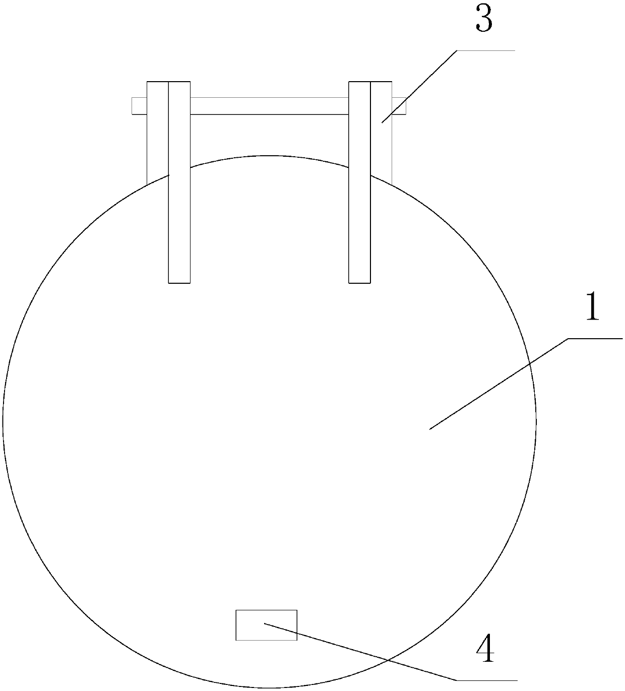
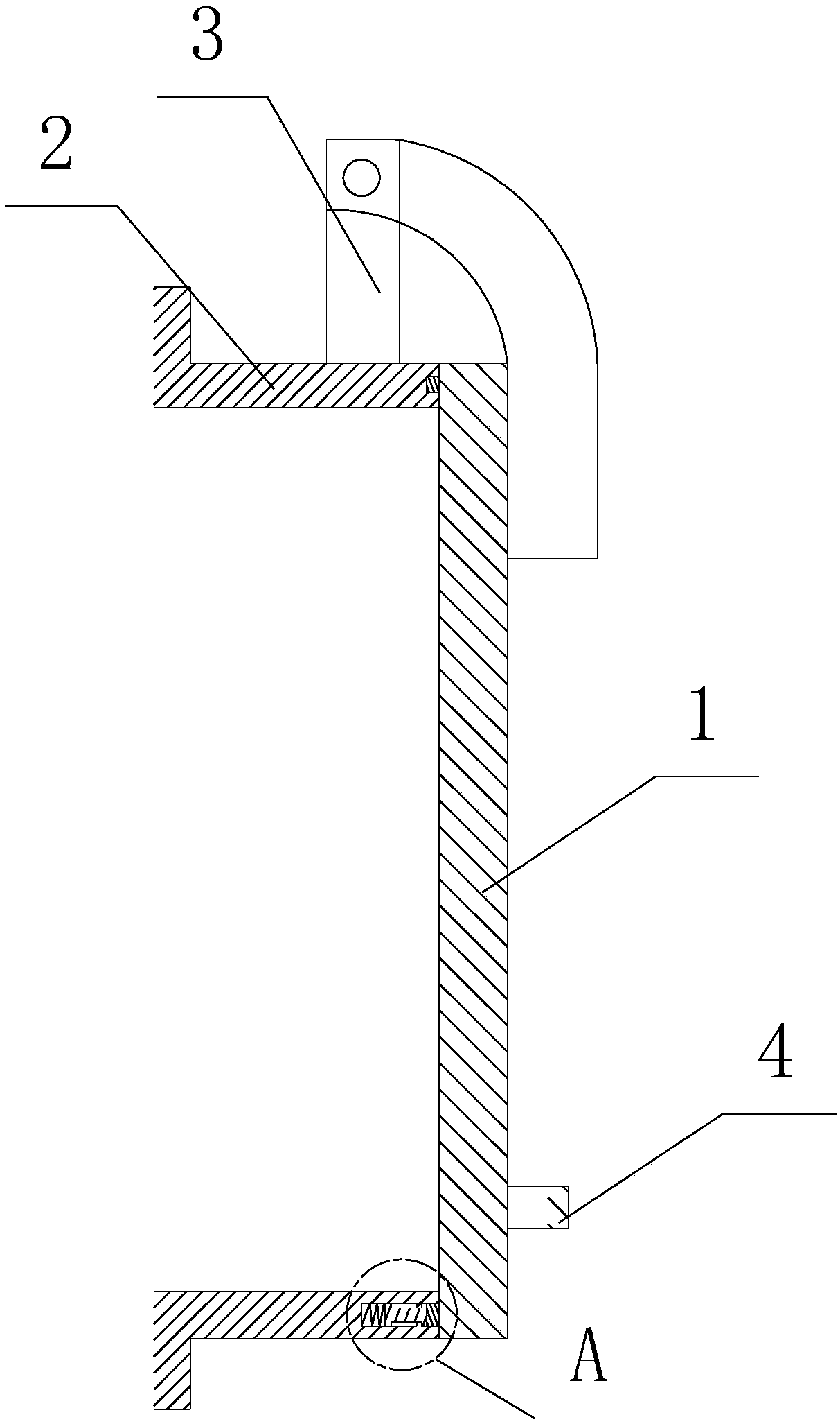
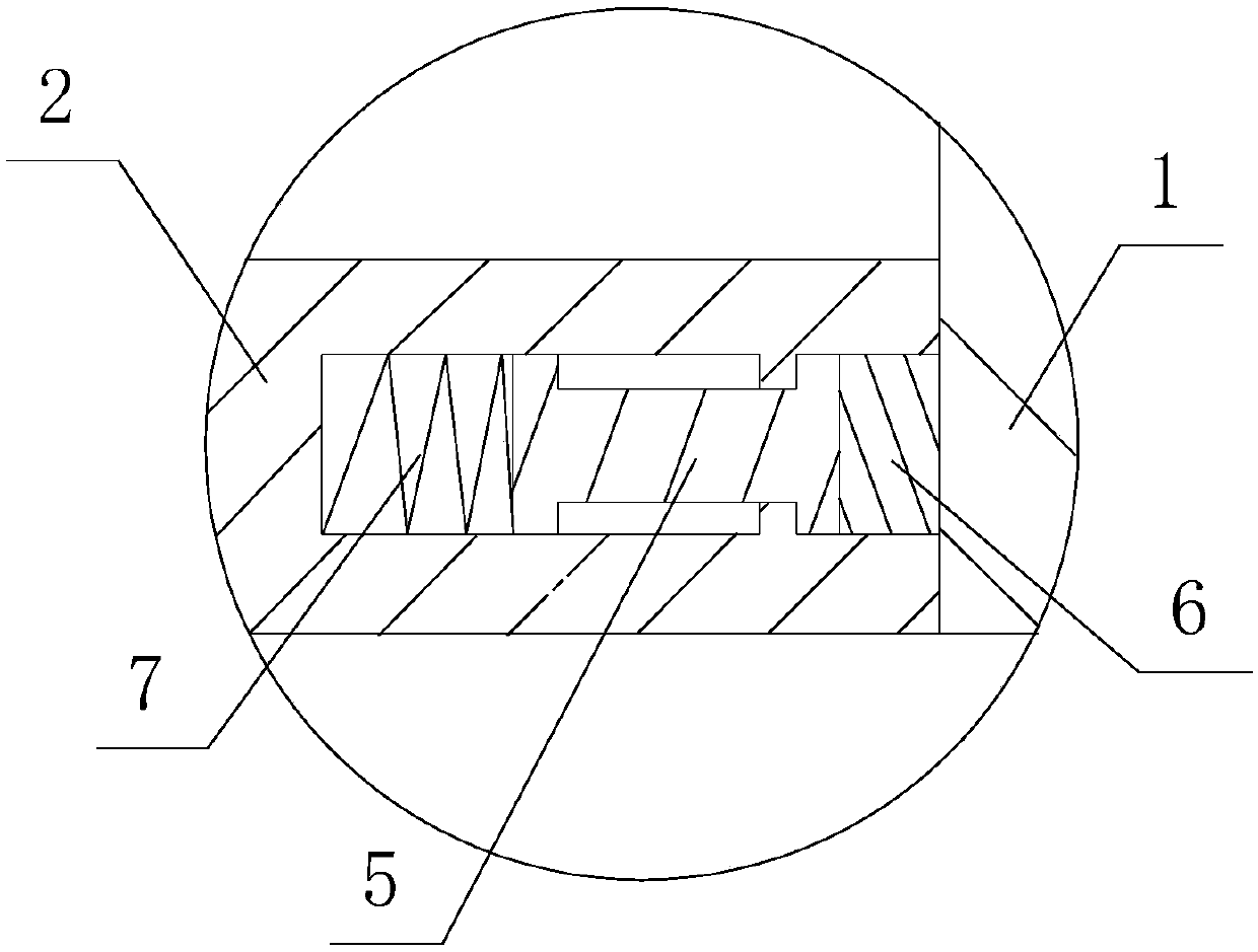
[0017] refer to Figure 1 to Figure 3 , the present invention provides a flap door with a buffer structure, which includes a door seat 2 and a door leaf 1, the upper end of the door seat 2 is provided with a hinged structure 3, the door leaf 1 is hinged on the door seat 2 through the hinged structure 3, the door seat The front end of the door leaf 2 is provided with an annular groove, and the rear end of the door leaf 1 is provided with a rubber ring 6 corresponding to the annular groove. There are chutes evenly distributed in the circumferential direction of the annular groove, and a buffer structure is arranged in the chute. The buffer structure includes Piston rod 5 and spring 7, the front and back ends of piston rod 5 are respectively provided with cushioning part and piston, and piston is slipped in the chute, and the end of piston is connected wi...


PUM


Abstract

The invention provides a flap valve with buffer structures. The flap valve comprises a valve seat and a valve page. A hinging structure is arranged at the upper end of the valve seat. The valve page is hinged to the valve seat through the hinging structure. The front end of the valve seat is provided with an annular groove. The rear end of the valve page is provided with a rubber ring matched withthe annular groove correspondingly. Sliding grooves are distributed in the annular groove circumferentially and evenly and are internally provided with the buffer structures. Each buffer structure comprises a piston rod and spring, wherein the front end and the rear end of the piston rod are provided with a buffer part and a piston correspondingly. The flap valve with the buffer structures is simple in structure, impact force during closing of the valve page can be buffered effectively, and the flap valve is protected very well while safe closing of the valve page is ensured so as to preventdamage of the flap valve during impact.

Description

technical field [0001] The invention relates to a flap door, in particular to a flap door with a buffer structure. Background technique [0002] The flap door is installed at the tail end of the drainage pipe, and is a check valve with the function of preventing external water from pouring back. At present, commonly used flap doors mainly include gravity type, floating box type and rollover type. The current flap door generally has the problem of impact force during the closing process. Under frequent high-intensity impact, problems such as cracking of the concrete structure and deformation of the flap door structure will occur, which will affect normal use. Contents of the invention [0003] 【1】Technical problems to be solved [0004] The technical problem to be solved by the present invention is to provide a flap door with a buffer structure which has a simple structure and can effectively buffer the impact force when the door leaves are closed. [0005] 【2】Technical ...

Claims


Application Information

Patent Timeline
Patent Type & Authority Applications(China)
IPC IPC(8): F16K15/03
CPCF16K15/03
Inventor 方芳
Owner 方芳
Why Eureka
Try Eureka