Drawer type fiber distribution frame

A fiber optic distribution frame and drawer-type technology, which is applied in the field of distribution frame design, can solve problems such as narrow operating space, interruption of optical cables, and insufficient redundancy of optical cables, and achieve the effect of safe and reliable connection

Pending Publication Date: 2018-06-01
ECONOMIC RES INST OF STATE GRID GANSU ELECTRIC POWER +2
View PDF0 Cites 1 Cited by
  • Summary
  • Abstract
  • Description
  • Claims
  • Application Information

AI Technical Summary

Problems solved by technology

However, in actual work, the optical cable at the back of the optical fiber distribution box often does not have enough margin during installation, resulting in the failure of the optical fiber distribution box to be pulled out smoothly. If the optical fiber distribution box is forcibly pulled out, the entire optical cable may be completely interrupted. This also allows the operation and maintenance personnel to only operate the fiber optic distribution box in a narrow enclosure
Due to the narrow operating space, it will also affect the operation accuracy of the operation and maintenance personnel. There may be phenomena such as the gaps on the fiber jumper not being aligned, and the jumper fiber being inserted into the wrong port, etc., which also cause certain hidden dangers to the safe operation of the optical communication system.

Method used


Image

  • Drawer type fiber distribution frame
  • Drawer type fiber distribution frame
  • Drawer type fiber distribution frame

Examples


Embodiment 1

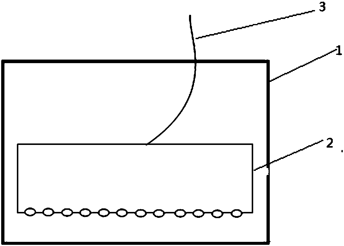
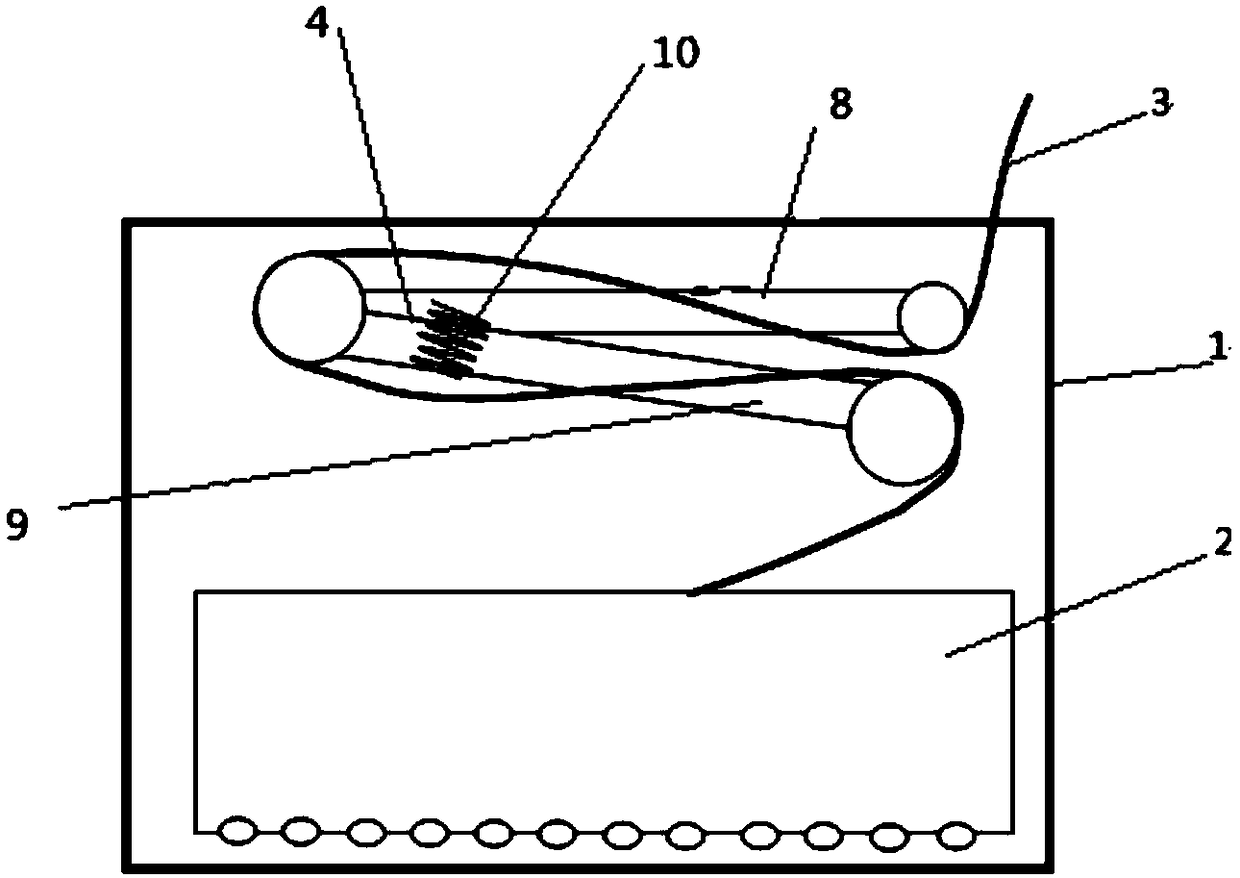
[0026] Drawer-type optical fiber distribution frame, in the existing drawer-type distribution frame such as figure 1 After making improvements such as figure 2 As shown, it includes a housing 1, a distribution box 2 and an optical fiber 3. The distribution box is arranged inside the housing 1, and the optical fiber 3 is arranged in the distribution box 2. The active connector of the margin, the optical fiber 3 is installed on the active connector 4, the optical fiber margin is the length of the optical fiber remaining outside the distribution box when the distribution box is pulled out or put in, and it can be avoided by changing the optical fiber margin When the optical fiber is pulled out because there is not enough margin, the optical fiber is broken.

Embodiment 2

[0028] combine 2 and image 3 , the biggest difference between the present invention and the traditional optical fiber distribution frame is the movable connector 4, the optical fiber 3 according to figure 2 Mounted on active connector 4.

[0029] The movable connector can automatically adjust the length of the optical fiber according to the position of the fiber tray, so that the fiber tray can be put in and out of the shell smoothly.

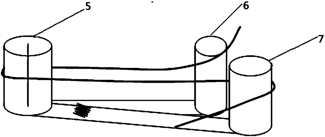
[0030] The movable connector is composed of cylinders 5, 6, 7, springs and connecting rods. The cylinders 5 and 6, and the cylinders 5 and 7 are connected by connecting rods. The cylinders 5 and 6 are fixed, and the cylinder 7 is movable. . Connecting rod 1 is between cylinder 5,6, connecting rod 2 is between cylinder 5,7, connects with spring between connecting rod 1,2. The middle of the cylinder 5 is fixed with screws, which can ensure that the cylinder 7 rotates around the cylinder 5, and the spring can automatically recover after the a...

Embodiment 3

[0034] Such as Figure 5 As shown, according to the actual situation, there may be multiple distribution boxes 2 in the housing 1. Designing a line card on the outside of the cylinder and putting different optical fibers into the line card can not only ensure clear and beautiful wiring, but also meet multiple requirements. The use of distribution boxes also ensures that there will be no knotting between different optical fibers.

[0035] The line card is designed on the outside of the cylinder, which can meet the use of multiple distribution boxes, and also ensures that there will be no knotting between different optical fibers

[0036] The line card includes a plurality of protrusions 11, grooves 12 are formed between the protrusions, and optical fibers 3 are placed in the grooves


PUM


Abstract

The invention discloses a drawer type fiber distribution frame mainly comprising a housing (1), a distribution box (2) and fibers (3); the distribution box is arranged in the housing (1); the fibers (3) are arranged in the distribution box (2); a fiber margin is arranged outside the distribution box; the drawer type fiber distribution frame also comprises a movable connector (4) used for changingthe fiber margin. The fiber distribution box can be plugged in a time saving and energy saving mode, thus preventing the fiber broken problems when the distribution box is forcibly pulled out from a conventional fiber distribution frame, and preventing jump fiber opening un-matching and jump fiber port wrong-plugging phenomenon caused by a narrow operation space.

Description

technical field [0001] The invention relates to the technical field of distribution frame design, in particular to a drawer-type optical fiber distribution frame. Background technique [0002] With the rapid development of the smart grid, the dependence on the optical communication network is also increasing. In the daily operation and maintenance of the optical communication network, a large number of fiber jumping operations need to be performed on the optical fiber distribution frame. In power systems, such as figure 1 As shown, the optical fiber distribution frame is composed of the distribution frame shell 1, the distribution box 2 and the fiber jumper 3. The distribution frame shell and the cabinet are fixed by screws, the distribution box is installed inside the shell, and the optical fiber is installed in the distribution box. . The distribution box is protected by the shell, so that the distribution box and the optical fiber are prevented from being disturbed by e...

Claims


Application Information

Patent Timeline
Patent Type & Authority Applications(China)
IPC IPC(8): G02B6/44
CPCG02B6/4452
Inventor 平常王仕俊杨云彭生江魏勇薛国斌杨晶妥建军杨国强廖翯王羿博
Owner ECONOMIC RES INST OF STATE GRID GANSU ELECTRIC POWER
Why Eureka
Try Eureka