High-speed pulse acquisition circuit with dynamic fault diagnosis capability

A technology for diagnosing faults and high-speed pulses, applied in electrical testing/monitoring, instruments, control/regulation systems, etc., can solve problems such as inability to absolutely determine field signal input, incorrectness, etc.

Active Publication Date: 2018-06-01
CHINA NUCLEAR CONTROL SYST ENG
View PDF7 Cites 7 Cited by
  • Summary
  • Abstract
  • Description
  • Claims
  • Application Information

AI Technical Summary

Problems solved by technology

But this kind of judgment cannot absolutely determine whether it is really a problem with the input channel of the module itself or whether the on-site signal input is incorrect or the signal is not transmitted correctly before entering the module.

Method used


Image

  • High-speed pulse acquisition circuit with dynamic fault diagnosis capability
  • High-speed pulse acquisition circuit with dynamic fault diagnosis capability

Examples


Embodiment Construction

[0020] The present invention will be described in detail below in conjunction with the accompanying drawings and specific embodiments.

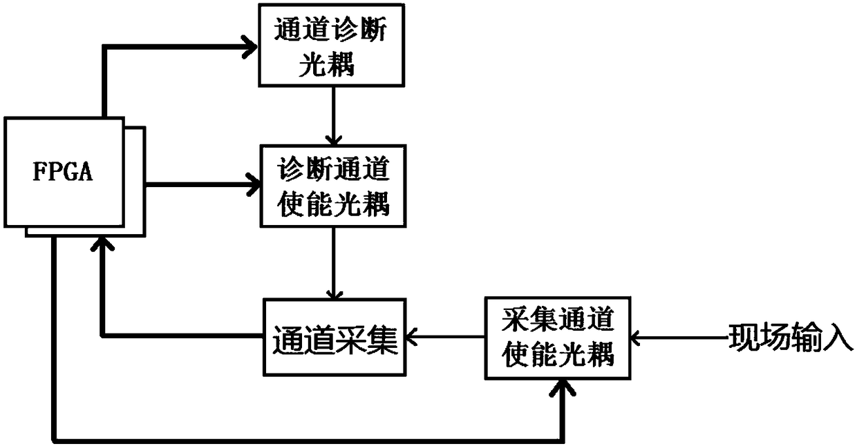
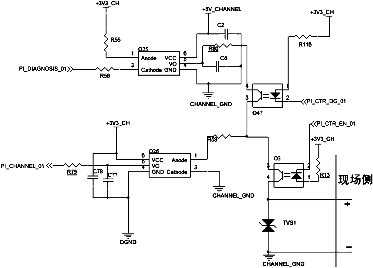
[0021] Such as figure 1 , figure 2 As shown, the channel diagnostic optocoupler module includes resistor R55, resistor R56, resistor R80, capacitor C2, capacitor C6 and optocoupler O25, the diagnostic channel enable optocoupler module includes optocoupler O47 and resistor R116, and the channel acquisition module includes resistor R79, Resistor R59, capacitor C78, ​​capacitor C77, and optocoupler O26. The acquisition channel enables the optocoupler module to include optocoupler O3, resistor R13, and diode TVS1. The FPGA module refers to connecting resistor R56, resistor R79, and the cathode of the diode at the input end of optocoupler O47. Coupling O3 input control signal of the cathode of the diode.

[0022] The digital quantity acquisition circuit is a pulse signal input acquisition, a dynamic diagnosis optocoupler circuit, a diagnosis ch...


PUM


Abstract

The invention belongs to the technical field of pulse signal acquisition and particularly relates to a high-speed pulse acquisition circuit with a dynamic fault diagnosis capability. The dynamic diagnosis is realized in following steps: an optocoupler O3 is controlled to close an input channel; an optocoupler O47 is then controlled to switch a diagnostic channel; an FPGA inputs pulse signals; at the time, the output of an optocoupler O25 is connected with the input side of an optocoupler O26; through switching the optocoupler O26, the pulse signals are transmitted to a 5 pin of the output endof the optocoupler O26; then, if the FPGA can correctly receive a corresponding pulse number, a normal state is judged, or otherwise, a fault state is judged. The hardware circuit can judge whether the high-speed pulse acquisition circuit acquires fault and can transmit the state information up in real time.

Description

technical field [0001] The invention belongs to the technical field of pulse signal acquisition, and in particular relates to a high-speed pulse quantity acquisition circuit with dynamic fault diagnosis capability. Background technique [0002] In the field of industrial control, nuclear power DCS system is an important branch. The nuclear power DCS system will specially design corresponding modules to collect the digital signals from the site to the DCS system, such as motor operating status, fault signal, nuclear reactor neutron radiation signal and other important signal inputs, and then send the collected signals to the control station for processing. Due to the characteristics of nuclear power plants, on-site signals need to be isolated from the DCS system to ensure that the safe operation of the entire main control station will not be affected in the event of a special damage to a certain part. At present, the most widely used and relatively stable solution for DCS s...

Claims


Application Information

Patent Timeline
Patent Type & Authority Applications(China)
IPC IPC(8): G05B23/02
CPCG05B23/0213G05B2219/24065
Inventor 冷强王嵚峰刘志凯梁成华王冬冀苗苗
Owner CHINA NUCLEAR CONTROL SYST ENG
Why Eureka
Try Eureka