A horizontal air-conditioning coil machine motor production shaft derusting recovery device

A technology for air conditioning coils and recycling devices, which is applied to grinding/polishing safety devices, metal processing equipment, manufacturing tools, etc., can solve problems such as low efficiency, poor effect, and rust on the surface of the rotating shaft, and achieves improved versatility, Improve the effect and avoid the effect of grinding dead corners

Active Publication Date: 2020-07-31
绍兴欣耀机电科技有限公司
View PDF8 Cites 0 Cited by
  • Summary
  • Abstract
  • Description
  • Claims
  • Application Information

AI Technical Summary

Problems solved by technology

[0002] The rotating shaft, as the name implies, is the shaft that must be used to connect the main parts of the product and is used to bear both bending moment and torque in the rotating work. In the air conditioner motor, the rotating shaft is an important component of the motor. During the production and processing of the rotating shaft , because the raw material of the shaft will be oxidized during the long-term storage process, the surface of the shaft will be rusted after oxidation, and the surface of the shaft needs to be derusted when finishing the shaft. The traditional derusting work mainly uses manual grinding, but manual grinding inefficient and ineffective

Method used


Image

  • A horizontal air-conditioning coil machine motor production shaft derusting recovery device
  • A horizontal air-conditioning coil machine motor production shaft derusting recovery device
  • A horizontal air-conditioning coil machine motor production shaft derusting recovery device

Examples


Embodiment Construction

[0021] The technical solution of this patent will be further described in detail below in conjunction with specific embodiments.

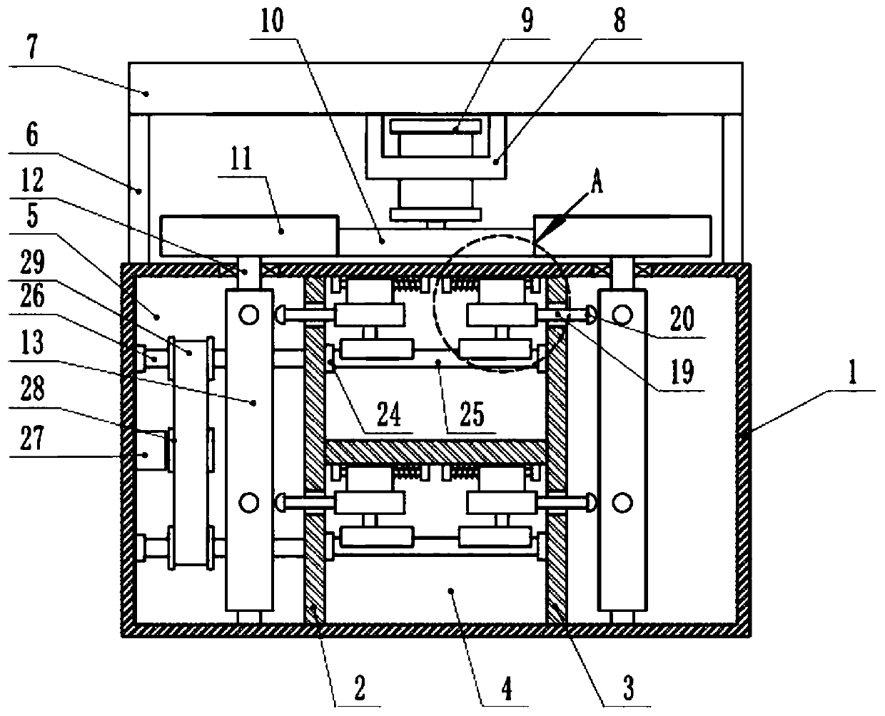
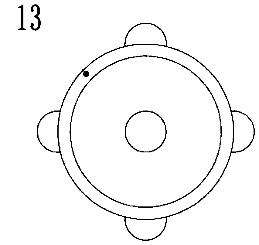
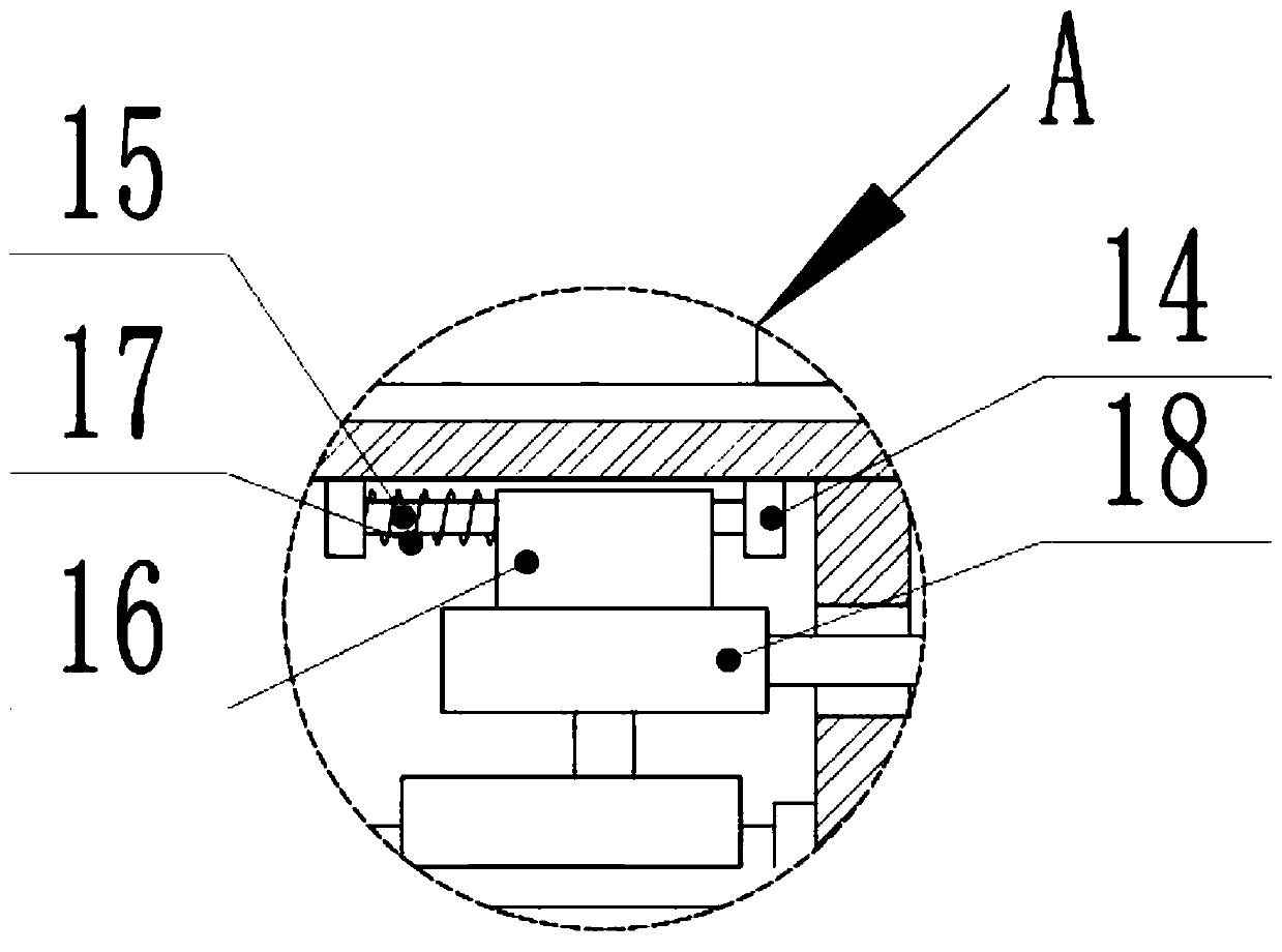
[0022] see Figure 1-4 , a horizontal air-conditioning coil machine motor production shaft rust removal recovery device, including a cabinet 1, a rust removal chamber 4, a device chamber 5, a first drive motor 9 and a second drive motor 27, the inside of the cabinet 1 is vertical The first partition 2 and the second partition 3 are installed, and the rust removal chamber 4 is formed between the first partition 2 and the second partition 3. The first partition 2 and the second partition 3 are connected with the left and right sides of the chassis 1. A device cavity 5 is formed between the inner walls, and a pillar 6 is symmetrically welded on the upper side of the chassis 1, and a top cover 7 is also provided on the upper side of the pillar 6, and the pillar 6 and the top cover 7 are also connected by welding, and the top cover 7 is lowered The sid...


PUM


Abstract

The invention discloses a rotating shaft rust removal and recovery device for horizontal air conditioner pipe coiler motor production. The rotating shaft rust removal and recovery device comprises a machine case, a rust removal cavity, a device cavity, a first driving motor and a second driving motor, wherein rotating cylinders are mounted on connecting shafts in an interference fit manner and positioned inside the machine case; semicircular bulges are arranged on the surfaces of the rotating cylinders; moving rods are slidably mounted inside fixing blocks; second springs are connected betweenthe upper ends of the moving rods and the inner walls of the fixing blocks; and grinding heads are welded with the lower ends of the moving rods. The rotating shaft rust removal and recovery device disclosed by the invention has the beneficial effects that through the action of first springs, the grinding heads can always be kept on the surface of a rotating shaft, thereby avoiding disjunction during a grinding process; meanwhile, rotating shafts of various diameters can be grinded, thereby greatly improving the university of the rotating shaft rust removal and recovery device; through the grinding heads, the surface of the rotating shaft can be subject to periodic mobile grinding and all-dimensional grinding, thereby avoiding blind angles during the grinding process as well as greatly improving the rotating shaft grinding and rust removal effects; and meanwhile, compared with the manual grinding operation, the rotating shaft rust removal and recovery device saves more time and effortas well as achieves higher reliability.

Description

technical field [0001] The invention relates to the field of rotating shaft processing, in particular to a rust removal and recovery device for rotating shafts used in the production of horizontal air-conditioning coil machine motors. Background technique [0002] The rotating shaft, as the name implies, is the shaft that must be used to connect the main parts of the product and is used to bear both bending moment and torque in the rotating work. In the air conditioner motor, the rotating shaft is an important component of the motor. During the production and processing of the rotating shaft , because the raw material of the shaft will be oxidized during the long-term storage process, the surface of the shaft will be rusted after oxidation, and the surface of the shaft needs to be derusted when finishing the shaft. The traditional derusting work mainly uses manual grinding, but manual grinding Inefficient and not very effective. Contents of the invention [0003] The obje...

Claims


Application Information

Patent Timeline
Patent Type & Authority Patents(China)
IPC IPC(8): B24B27/033B24B55/12
CPCB24B27/033B24B55/12
Inventor 何辉
Owner 绍兴欣耀机电科技有限公司
Why Eureka
Try Eureka