Unlock instant, AI-driven research and patent intelligence for your innovation.

Concrete stirring equipment

A technology for concrete and equipment, applied in the field of concrete mixing equipment, can solve the problems of improper mixing, large space occupation and high manufacturing cost, and achieve the effects of convenient performance testing, improving mixing quality and improving production efficiency

Active Publication Date: 2018-06-05
广州市建筑集团混凝土有限公司
View PDF8 Cites 4 Cited by
  • Summary
  • Abstract
  • Description
  • Claims
  • Application Information

AI Technical Summary

Problems solved by technology

[0002] At present, in the concrete mixing work, due to the limitation of the site, various materials (these materials include coarse aggregate, fine aggregate, cement, etc.) cannot be fully mixed, or the role of each part cannot be fully exerted due to improper mixing. It will make the strength of the building using the concrete not guaranteed, and it will cause more or less quality problems in the process of use.
Moreover, the existing concrete mixing machine takes up a large space, is noisy, has certain dangers, and has high manufacturing costs. Therefore, a concrete mixing machine with a small footprint, low cost, multiple functions and high safety is designed. device is necessary
[0003] The existing concrete mixing device includes a mixing drum, the mixing drum is axially arranged with a stirring shaft, the stirring shaft is driven by a motor, and several blades are arranged on the stirring shaft, the disadvantage of this concrete mixing device is that: when the stirring shaft rotates , the blades stir the concrete to make the concrete mix, but due to the distance between the blades, the concrete between the blades cannot be stirred when the blades rotate, so that the local mixing effect of the entire concrete is not good

Method used


Image

  • Concrete stirring equipment
  • Concrete stirring equipment
  • Concrete stirring equipment

Examples


Embodiment approach

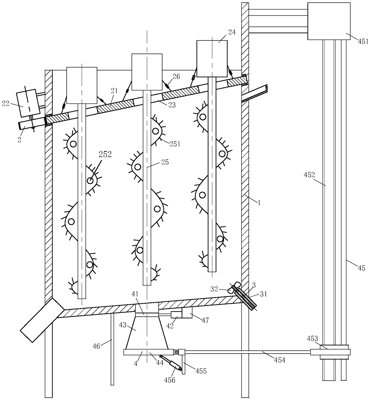
[0039] As an embodiment of the present invention, the cover plate 21 is arranged obliquely. When the cover plate 21 rotates, it can drive the stirring motor 24 and the stirring shaft 25 to rotate, and make the stirring shaft 25 move up and down relative to the housing 1, so that the stirring is more efficient. full.

[0040] As an embodiment of the present invention, the agitating shaft 25 is provided with a helical agitating blade 251, and the edge of the agitating blade 251 is provided with irregularly arranged steel needles, which are used to scratch part of the agglomerated concrete; There is a cavity inside the shaft 25; a condensing pipe is arranged in the cavity, and by controlling the condensing pipe, selective cooling is applied to the mixing of different types of concrete, and because the position of the stirring shaft 25 is changeable, it makes the cooling of the concrete more effective. Fully, improve production efficiency. Further, the stirring blade 251 is provi...


PUM


Abstract

The invention belongs to the technical field of concrete processing and particularly relates to concrete stirring equipment. The concrete stirring equipment comprises a shell, a stirring unit, a cleaning unit and a detection unit, wherein the stirring unit is rotatably connected to the upper part of the shell; the stirring unit comprises a cover plate, a rotating motor, a rotating plate, a stirring motor and stirring shafts; the bottom of the shell inclines towards one side, and the cleaning unit is arranged at the lowest point of the shell, comprises a hollow motor, rotating blades, a pipeline and a control valve and is used for cleaning and assisting stirring; and the detection unit is arranged at the bottom of the shell, comprises a blocking plate, an air cylinder, a slump bucket, a baffle, a lifting module and a scale plate and is used for detecting the stirring condition of concrete. By adequately arranging the stirring unit, the stirring shafts can move up and down relatively tothe shell in the rotation process of the stirring unit, so that the concrete can be relatively adequately stirred; and meanwhile, the detection unit is integrated and can be used for conveniently detecting the performance of the stirred concrete, so that the production efficiency is improved.

Description

technical field [0001] The invention belongs to the technical field of concrete processing, in particular to a concrete mixing equipment. Background technique [0002] At present, in the concrete mixing work, due to the limitation of the site, various materials (these materials include coarse aggregate, fine aggregate, cement, etc.) cannot be fully mixed, or the role of each part cannot be fully exerted due to improper mixing. The strength of the building using the concrete cannot be guaranteed, and quality problems will be more or less produced during use. Moreover, the existing concrete mixing machine takes up a large space, is noisy, has certain dangers, and has high manufacturing costs. Therefore, a concrete mixing machine with a small footprint, low cost, multiple functions and high safety is designed. device is very necessary. [0003] The existing concrete mixing device includes a mixing drum, the mixing drum is axially arranged with a stirring shaft, the stirring s...

Claims


Application Information

Patent Timeline
IPC IPC(8): B28C5/16B28C5/08B28C7/04B28C7/16
CPCB28C5/0806B28C5/16B28C7/04B28C7/16
Inventor 王本勋葛旭樊雪花
Owner 广州市建筑集团混凝土有限公司