Crank shaft roller structure, compressor and air conditioner
A roller and crankshaft technology, applied in the field of compressors, can solve the problems of poor assembly coaxiality, clamping and clamping of the upper and lower flanges of the crankshaft, and achieve the effects of improving performance, reducing friction, and reducing frictional loss of power.
- Summary
- Abstract
- Description
- Claims
- Application Information
AI Technical Summary
Problems solved by technology
Method used
Image

Examples
Embodiment 1
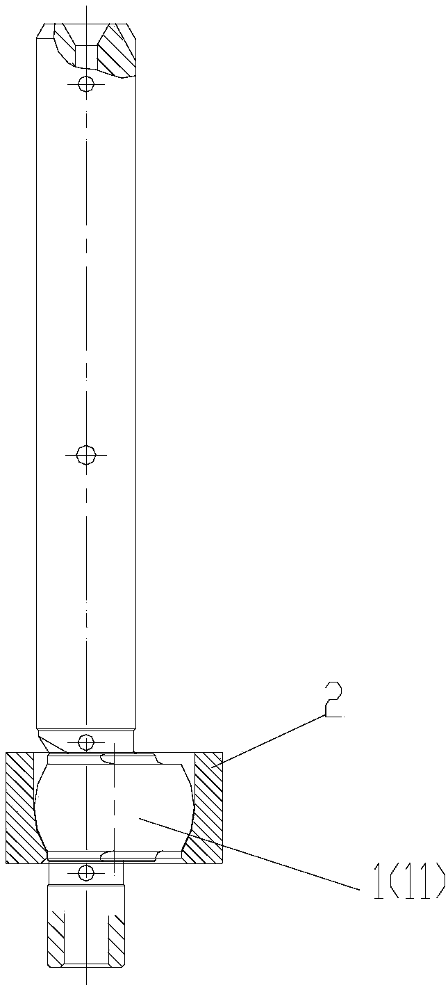
[0042] like figure 1 As shown, the present invention provides a crankshaft roller structure, which includes:
[0043] Crankshaft 1 with eccentric portion 11;
[0044] Roller 2, which is sleeved on the outer circumference of the eccentric portion 11;
[0045] And the outer peripheral surface of the eccentric portion 11 is a first spherical surface, the inner peripheral surface of the roller 2 is a second spherical surface, and the second spherical surface is adapted to the first spherical surface, so that the The roller 2 can be driven to rotate by the eccentric portion 11 .
[0046] By setting the outer peripheral surface of the eccentric portion as a first spherical surface, the inner peripheral surface of the roller is a second spherical surface, and the second spherical surface is adapted to the first spherical surface, so that The rollers can be driven by the eccentric part to rotate, which can make the contact between the crankshaft and the rollers a spherical contact ...
Embodiment 2
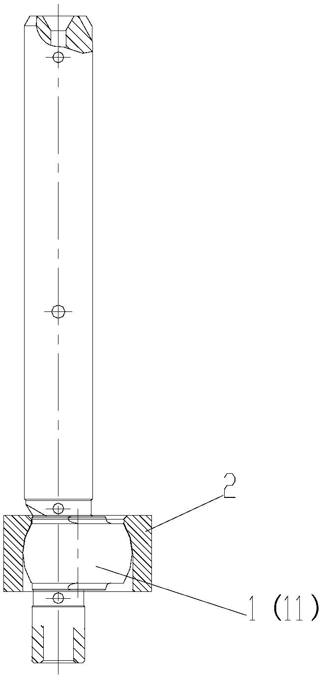
[0053] like figure 2 As shown, in this embodiment, on the basis of embodiment 1, the specific structure of the roller is replaced accordingly, and the others are the same as in embodiment 1. The axis of the roller is along the vertical direction, and along the direction of the axis of the roller, the diameter of the inner peripheral surface of the roller perpendicular to the axis of the roller decreases gradually from bottom to top, and the lower end surface of the roller Opening diameter = diameter D2 of the second spherical surface. The eccentric part of the crankshaft is designed from the original cylindrical shape to a spherical shape, and the ball diameter of the eccentric part of the crankshaft D1 = 0.6 times the diameter of the cylinder; the interior of the roller is designed from the original cylindrical shape to a spherical shape, and the inner ball diameter of the roller D2 = the ball diameter of the eccentric part of the crankshaft + 0.02 mm. The diameter of the ...
Embodiment 3
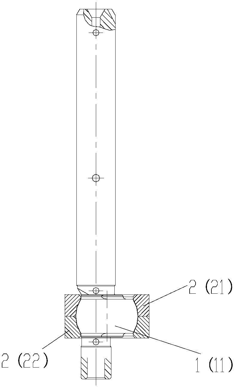
[0055] like image 3 As shown, in this embodiment, on the basis of embodiment 1, the specific structure of the roller is replaced accordingly, and the others are the same as in embodiment 1.
[0056] The roller 2 is a split structure, including more than two roller blocks distributed along the axis of the roller. This is the preferred structural form of the crankshaft roller structure of the present invention. By adopting the roller of the split structure, the roller and the eccentric part of the crankshaft can be partially engaged and then spliced together, preventing the eccentric part of the crankshaft from The diameter is larger than the diameter of the upper and lower end faces of the roller and cannot be assembled.
[0057] Preferably,
[0058] The axes of the rollers are along the vertical direction, and the roller blocks include a first roller block 21 located axially above and a second roller block 22 located axially below, the first roller block 21 The lower end...
PUM
 Abstract
Description
Claims
Application Information
 - R&D
- Intellectual Property
- Life Sciences
- Materials
- Tech Scout
- Unparalleled Data Quality
- Higher Quality Content
- 60% Fewer Hallucinations
Browse by: Latest US Patents, China's latest patents, Technical Efficacy Thesaurus, Application Domain, Technology Topic, Popular Technical Reports.
© 2025 PatSnap. All rights reserved.Legal|Privacy policy|Modern Slavery Act Transparency Statement|Sitemap|About US| Contact US: help@patsnap.com