Thermal correcting connection assembly

A technology for connecting components and thermal correction, applied in the direction of connecting components, shrinking connections, pins, etc., can solve problems such as damage to tooling, difficulty in disassembly, etc., and achieve the effects of saving resources, avoiding difficulty in disassembly, and facilitating hoisting

Inactive Publication Date: 2018-06-05
XIAN AEROSPACEMOTOR MACHINE FACTORY
View PDF7 Cites 4 Cited by
  • Summary
  • Abstract
  • Description
  • Claims
  • Application Information

AI Technical Summary

Problems solved by technology

[0003] In order to overcome the disassembly difficulties existing in the prior art, which may even cause d

Method used


Image

  • Thermal correcting connection assembly
  • Thermal correcting connection assembly
  • Thermal correcting connection assembly

Examples


Example Embodiment

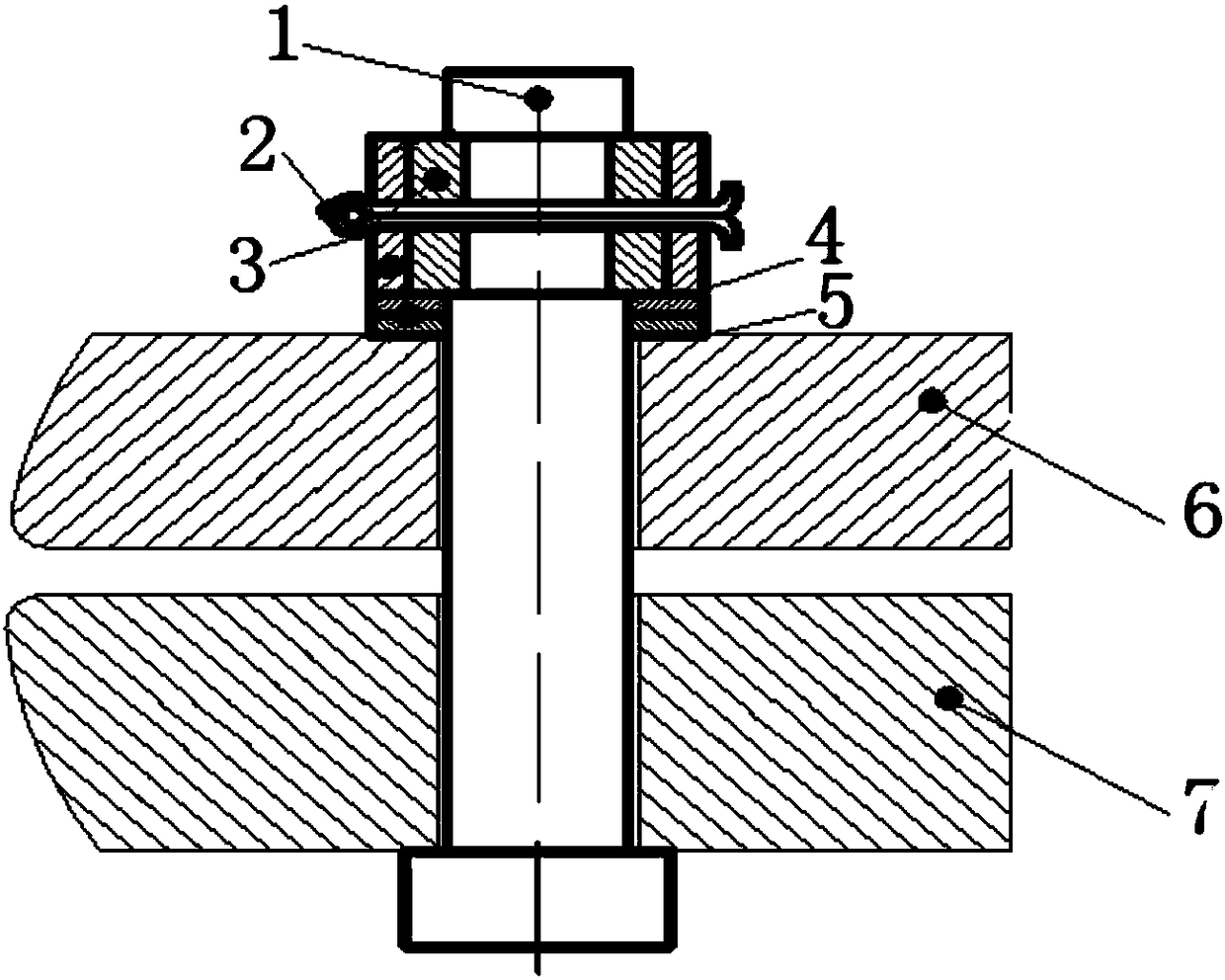
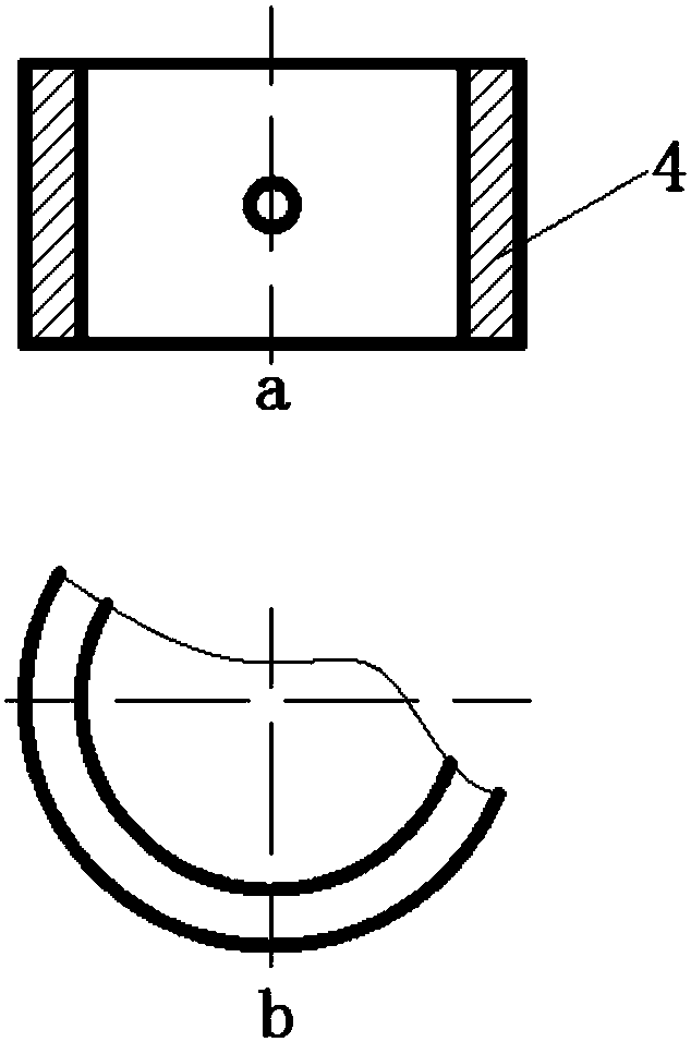
[0024] This embodiment is a connection assembly for thermally correcting warping of hemispherical parts with a wall thickness less than 10mm, including a connecting rod 1 , a cotter pin 2 , a clamp 3 , a snap ring 4 and an adjustment pad 5 . Wherein, the clamp 3 is embedded in the installation groove at the upper end of the connecting rod 1, and the clamp ring 4 is sleeved on the outer circumferential surface of the clamp; the cotter pin 2 passes through the clamp ring, the clamp and the connecting rod, and the The three are connected. The distance between the heat-shaping connection component and the surface of the connected part is adjusted by adjusting the pad 5 .

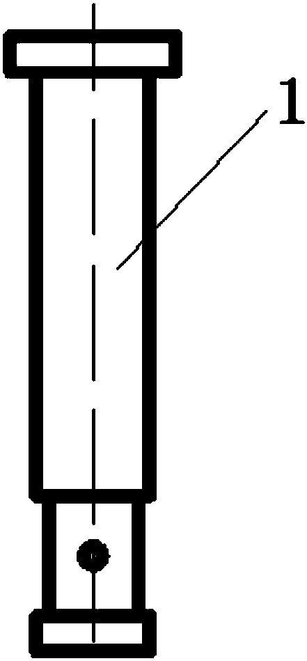
[0025] The length of the shaft of the connecting rod 1 is greater than the sum of the heights of the connected upper platen 6 and the lower platen 7; the shaft of the connecting rod passes through the center hole of the upper platen 6 and the center hole of the lower platen 7 . The outer peripheral surface of ...


PUM


Abstract

A thermal correcting connection assembly comprises a connection rod, a cotter pin, a clamping hoop, a clamping ring and an adjusting pad, wherein the clamping hoop is embedded in an installing groovein the upper end of the connection rod in a sleeved manner, and the clamping ring is arranged on the peripheral surface of the clamping loop in a sleeving manner; and the cotter pin penetrates the clamping ring, the clamping loop and the connection rod to fixedly connect the clamping ring, the clamping loop and the connection rod. The interval between the thermal correcting connection assembly andthe surface of a connected piece is adjusted through the adjusting pad. During thermal correcting, the thermal correcting connection assembly is inserted into a connection hole of the thermal correcting tool to be connected with the thermal correcting tool, the adjusting gasket is selected according to the actual distance between the installing groove of the connection rod and the work face of the thermal correcting tool, the clamping hoop is installed in the installing groove of the connection rod, the outer side of the clamping loop is sleeved with the clamping ring so that the clamping loop can be fixed, finally, the cotter pin is inserted into a through hole of the clamping ring, the clamping hoop and the connection rod, and the clamping ring, the clamping hoop and the connection rodare connected into a whole. The thermal correcting connection assembly achieves the purpose of connection of the thermal correcting tool, the disassembling difficulty, caused by thermal correcting, ofthe thermal correcting tool can be avoided, the production efficiency is improved, and the production cost is reduced.

Description

technical field [0001] The invention relates to the mechanical processing industry, in particular to a connection device for heat-correcting tooling. Background technique [0002] Thermal shaping process is a relatively common auxiliary process in the machining industry, which is used to eliminate the deformation of parts caused by internal stress during processing, so as to further improve the dimensional accuracy of parts. The thermal calibration process generally provides prestress for thermal calibration through bolt connection. In this connection method, after one to three thermal calibrations, the thread deforms, so that the calibration tool cannot be disassembled, and the calibration tool can only be disassembled by destroying the bolts. Shaped tooling, which not only greatly reduces production efficiency, but also causes waste of resources. Patent "A Thermal Calibration Tooling Fixture for Busbar Straightness of Shell Products" (patent application number: 2014207178...

Claims


Application Information

Patent Timeline
IPC IPC(8): F16B4/00F16B13/06B21D37/16
CPCB21D37/16F16B4/00F16B13/04F16B13/10
Inventor 白小雷龚军善杨延涛赵琳瑜牟少正温树斌罗卉
Owner XIAN AEROSPACEMOTOR MACHINE FACTORY
Why Eureka
Try Eureka