Multifunctional heat supply cabinet

A multi-functional heating pipe technology, applied in the field of furniture products, can solve the problems of low heat dissipation efficiency, low heat dissipation efficiency, large weight and volume, etc., and achieve the effects of reducing energy consumption, high transmission efficiency, and improving air quality

Inactive Publication Date: 2018-06-05
TIANJIN XIANGTAI FURNITURE
View PDF0 Cites 1 Cited by
  • Summary
  • Abstract
  • Description
  • Claims
  • Application Information

AI Technical Summary

Problems solved by technology

[0002] At present, the heating radiators commonly used in existing households are all old-fashioned radiators, and the old-fashioned radiators are cast iron radiators. The reason why cast iron radiators have been used for a long time is because they have the advantages of simple structure, low manufacturing cost, and cheap market price. However, other There are disadvantages such as low heat dissipation efficiency, large weight and volume, inconvenient installation, and unsightly appearance. Therefore, in recent years, old-fashioned cast iron radiators have been replaced by steel radiators; however, due to the continuous increase in housing prices in recent years, users The demand for device space utilization is increasing year by year, and the adverse effects of the radiator on the wall, such as blackening, and various problems caused by low heat dissipation efficiency, how to upgrade the old-fashioned radiator so that it can increase the existing family. Space utilization and improving heat dissipation efficiency are the mainstream development direction of the furniture market today

Method used


Image

  • Multifunctional heat supply cabinet
  • Multifunctional heat supply cabinet
  • Multifunctional heat supply cabinet

Examples


Embodiment Construction

[0021] In order to further understand the content, characteristics and effects of the present invention, the following examples are given, and detailed descriptions are given below with reference to the accompanying drawings. It should be noted that this embodiment is descriptive, not restrictive, and cannot thereby limit the protection scope of the present invention.

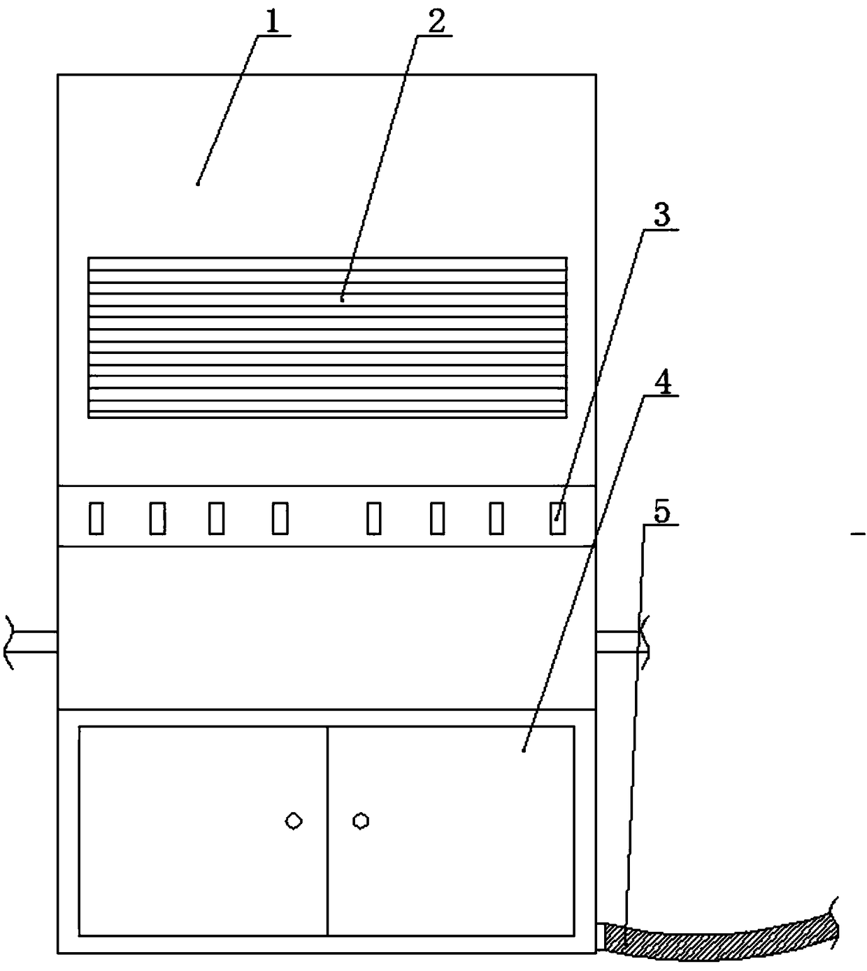
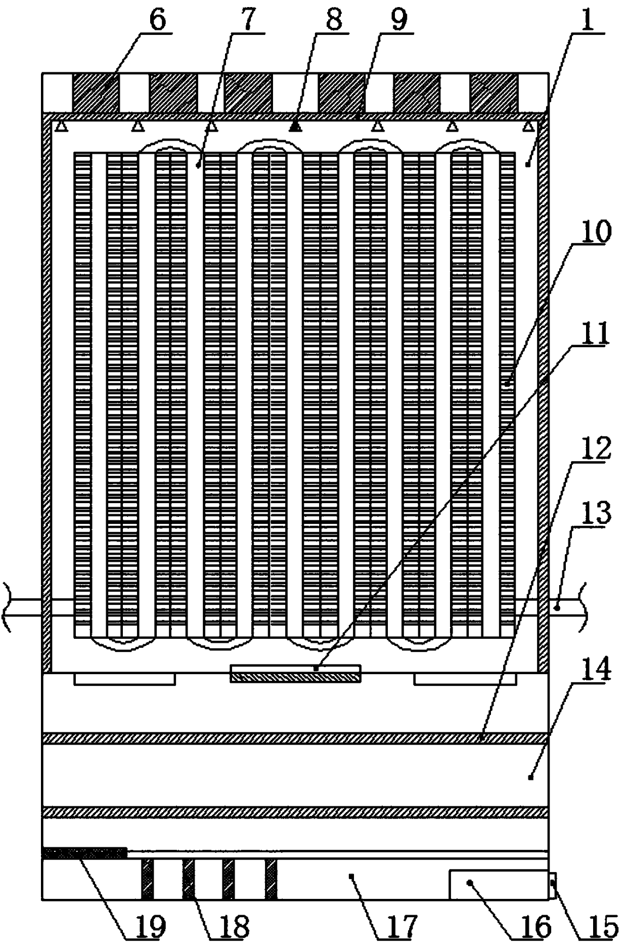
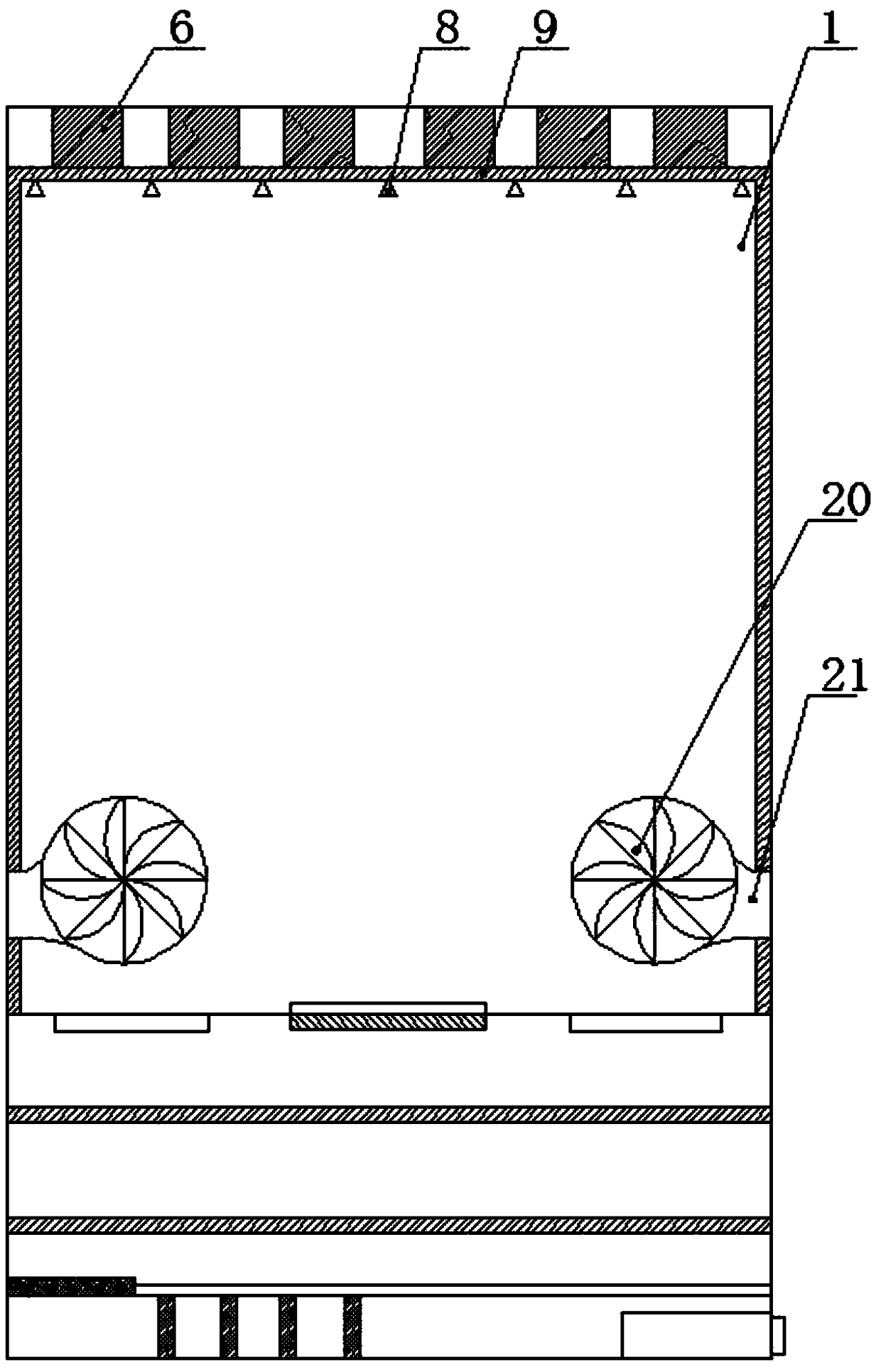
[0022] A multifunctional heating cabinet, comprising a heating box 1, a heat exchange tube 7 is set in the heating box, and the heat exchange tube is connected with a household heating pipe 13, and a plurality of Silent fan 6. A heat supply port 2 compounded with activated carbon adsorption layer is formed above the outer end surface of the heat supply box. Bottom blower fans 20 arranged obliquely upwards are formed on both sides of the bottom, and the air enters through the lateral ventilation holes 21 communicating with the outside; there are multiple sets of heat exchange fins 10 connected to both sides of t...


PUM


Abstract

A multifunctional heat supply cabinet comprises a heat supply box. The top end of the heat supply box is provided with a plurality of noiseless draught fans. The upper portion of the outer end face ofthe heat supply box is provided with a heat supply opening composited with an activated carbon adsorption layer. The heat supply opening is controlled by an electric control cover plate to be openedor closed, wherein the electric control cover plate is arranged in the heat supply box in a sliding manner. The two sides of the bottom of the heat supply box are provided with bottom blower fans which are obliquely and upwards arranged, and air entering is achieved through lateral air holes communicating with the exterior. The two sides of a heat exchanging pipe communicate with a plurality of heat exchanging fins, and the inclination directions of the fins are perpendicular to the wind directions of the bottom blower fans. The heat supply box is internally provided with a photocatalyst layerin a composited manner. The top of the heat supply box is further provided with a plurality of ultraviolet light sources. According to the multifunctional heat supply cabinet, defects in the prior art are overcome, photocatalyst treatment is carried out in the heat supply box, air with free radicals is heated by the heat exchanging fins, and the heated air is blown to the hot air holes through the bottom blower fans which are obliquely and upwards arranged on the bottom of the heating part; and compared with a traditional heat pipe for exchanging heat, the multifunctional heat supply cabinetis simpler and higher in transmission efficiency.

Description

technical field [0001] The invention relates to the technical field of furniture articles, in particular to a multifunctional heating cabinet. Background technique [0002] At present, the heating radiators commonly used in existing households are all old-fashioned radiators, and the old-fashioned radiators are cast iron radiators. The reason why cast iron radiators have been used for a long time is because they have the advantages of simple structure, low manufacturing cost, and cheap market price. However, other There are disadvantages such as low heat dissipation efficiency, large weight and volume, inconvenient installation, and unsightly appearance. Therefore, in recent years, old-fashioned cast iron radiators have been replaced by steel radiators; however, due to the continuous increase in housing prices in recent years, users The demand for device space utilization is increasing year by year, and the adverse effects of the radiator on the wall, such as blackening, and...

Claims


Application Information

Patent Timeline
Patent Type & Authority Applications(China)
IPC IPC(8): F24D19/06F24D19/08
CPCF24D19/064F24D19/08
Inventor 王生
Owner TIANJIN XIANGTAI FURNITURE
Why Eureka
Try Eureka