Oscillation wave detection transformer winding deformation circuit and method

A transformer winding and oscillatory wave technology, which is applied in the field of transformer winding state evaluation and detection, can solve the problems that the slight deformation of the winding is not easy to find, the measurement voltage of the frequency response method is low, and the measurement results are not intuitive, etc., achieving high accuracy and high detection signal. Strong, high voltage effect

Pending Publication Date: 2018-06-05
YUNNAN POWER GRID CO LTD ELECTRIC POWER RES INST
View PDF6 Cites 13 Cited by
  • Summary
  • Abstract
  • Description
  • Claims
  • Application Information

AI Technical Summary

Problems solved by technology

The existing main detection methods for winding deformation include frequency response method and impedance method. The frequency response method has low measurement voltage, unintuitive measurement results, and cannot be quantitatively judged. The horizontal and vertical comparison of the frequency response curve can make a comprehensive judgment; the short-circuit impedance method is the earliest detection method for transformer winding deformation, but it is not easy to find out the slight deformation of the winding

Method used


Image

  • Oscillation wave detection transformer winding deformation circuit and method
  • Oscillation wave detection transformer winding deformation circuit and method

Examples


Embodiment 1

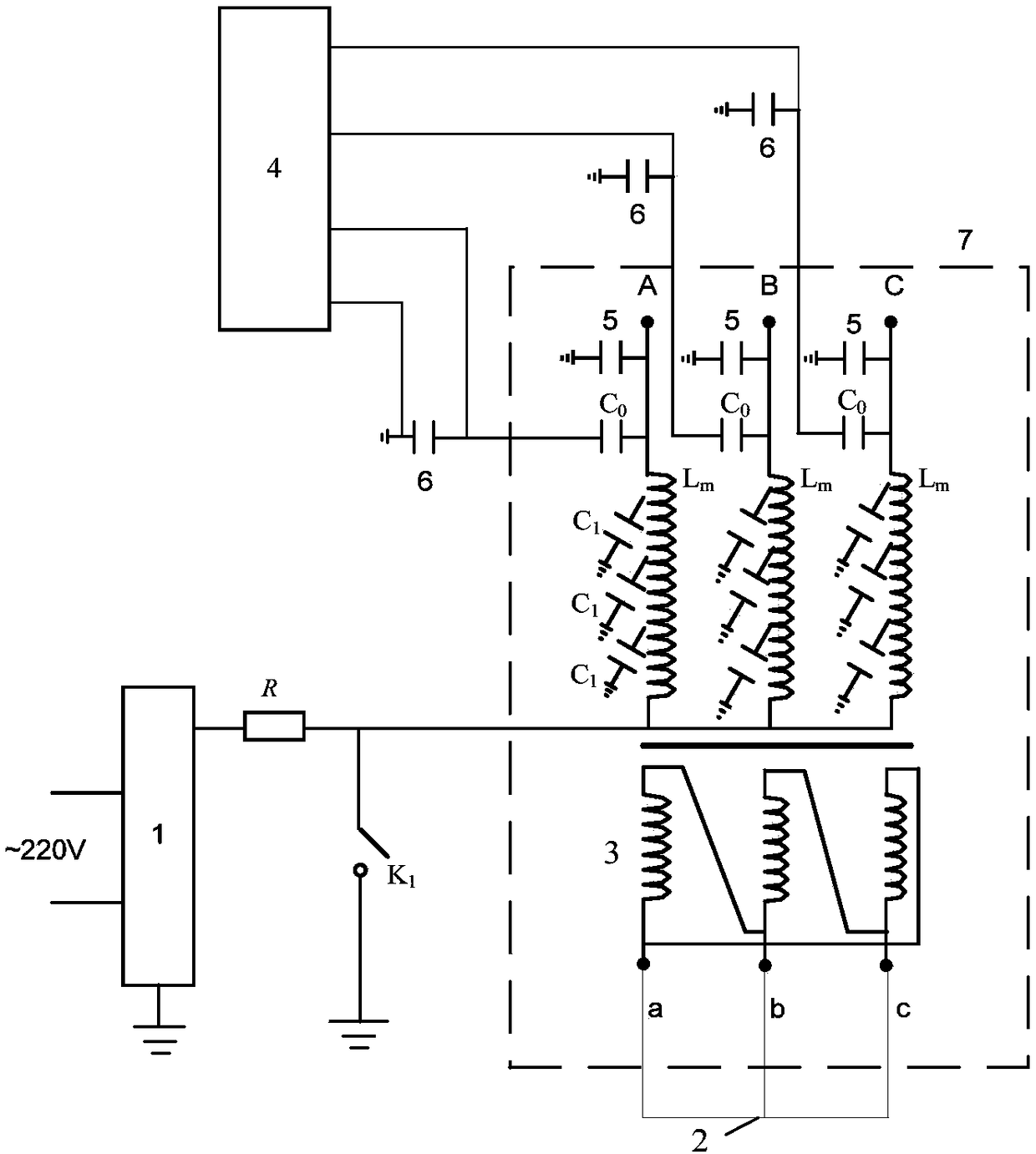
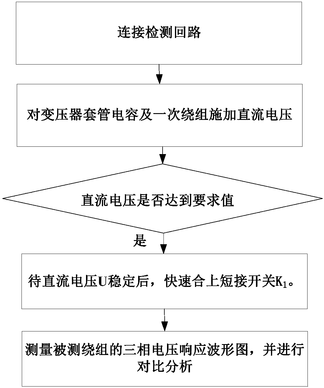
[0032] Embodiment 1: Stray capacitance C of transformer 7 to ground 1 , bushing capacitance C 0 and primary winding L mFor the leakage reactance oscillation circuit of the secondary winding 3, the secondary winding 3 of the transformer 7 is short-circuited by the short-circuit wire 2, and the primary winding L of the transformer 7 m The three-phase neutral point is connected to the DC high voltage generator 1, the DC high voltage generator 1 is grounded, and the DC high voltage generator 1 is connected to the short circuit switch K 1 Set protection resistor R between, short switch K 1 One end is electrically connected to the DC high voltage generator 1 and the primary winding L m The other end is grounded, and the DC high voltage generator 1 is connected to a 220V AC power supply. Primary winding L of transformer 7 m The three-phase first ends of the transformer 7 are suspended, or the primary winding L of the transformer 7 m The first ends of the three phases are all el...

Embodiment 2

[0033] Embodiment 2: Stray capacitance C of transformer 7 to ground 1 , bushing capacitance C 0 and primary winding L m For the excitation impedance oscillation circuit of the secondary winding 3, the secondary winding 3 does not need to be short-circuited, and the primary winding L of the transformer 7 m The three-phase neutral point is connected to the DC high voltage generator 1, the DC high voltage generator 1 is grounded, and the DC high voltage generator 1 is connected to the short circuit switch K 1 Set protection resistor R between, short switch K 1 One end is electrically connected to the DC high voltage generator 1 and the primary winding L m The other end is grounded, and the DC high voltage generator 1 is connected to a 220V AC power supply. Primary winding L of transformer 7 m The three-phase first ends of the transformer 7 are suspended, or the primary winding L of the transformer 7 m The first ends of the three phases are all electrically connected to a co...


PUM


Abstract

The invention discloses an oscillation wave detection transformer winding deformation circuit and a method. The oscillation wave detection transformer winding deformation circuit comprises a direct current high voltage power supply, wherein the direct current high voltage power supply is connected to a three phase neutral point of a primary winding; a short circuit switch is arranged between the direct current high voltage power supply and the primary winding; one terminal of the short circuit switch is electrically connected to a position between the direct current high voltage power supply and the primary winding; the other terminal of the short circuit switch is grounded; the end screen of a bushing capacitor of each phase of the primary winding is electrically connected with a voltage-dividing capacitor; the two terminals of the voltage-dividing capacitor are connected to a waveform measurement and analysis device; all the voltage-dividing capacitors are grounded. The oscillation wave detection transformer winding deformation circuit forms a leakage reactance or excitation impedance oscillation circuit of a ground stray capacitor, the bushing capacitors and the primary windingto a secondary winding through closed grounding of the short circuit switch, measures a three phase voltage response curve of the primary winding through the waveform measurement and analysis device,analyzes and compares the three phase voltage response curve to judge whether a transformer winding is deformed. The oscillation wave detection transformer winding deformation circuit is applicable totransformer winding deformation potential fault detection.

Description

technical field [0001] The present application relates to the technical field of transformer winding state evaluation and detection, in particular to a circuit and method for detecting transformer winding deformation by an oscillatory wave. Background technique [0002] The axial or radial dimensional changes of power transformer windings under the action of mechanical force or electrodynamic force are usually characterized by local twisting, bulging or displacement of windings. When the transformer is subjected to short-circuit current impact or impact during transportation, winding deformation may occur, which will directly affect the safe operation of the transformer. According to statistics, the latent fault of 110kV and above power transformer winding with slight deformation is one of the main causes of power transformer damage and grid failure. The existing main detection methods for winding deformation include frequency response method and impedance method. The frequ...

Claims


Application Information

Patent Timeline
Patent Type & Authority Applications(China)
IPC IPC(8): G01R31/06
CPCG01R31/72
Inventor 刘红文王科李昊
Owner YUNNAN POWER GRID CO LTD ELECTRIC POWER RES INST
Why Eureka
Try Eureka