A fuel cell power generation system using liquid oxygen as oxidant
What is AI technical title?
AI technical title is built by Patsnap AI team. It summarizes the technical point description of the patent document.
A fuel cell and oxidant technology, applied in the direction of fuel cells, fuel cell additives, fuel cell heat exchange, etc., can solve the problem that liquid oxygen cannot be directly generated by fuel cells, and achieve low cost, fast filling speed, and way simple effect
Active Publication Date: 2020-06-16
DALIAN INST OF CHEM PHYSICS CHINESE ACAD OF SCI
View PDF7 Cites 6 Cited by
Summary
Abstract
Description
Claims
Application Information
AI Technical Summary
This helps you quickly interpret patents by identifying the three key elements:
Problems solved by technology
Method used
Benefits of technology
Problems solved by technology
[0004] However, liquid oxygen cannot be directly used for fuel cell power generation. It needs to be vaporized before use. The vaporization process requires heat from the external environment.
Method used
Image
Click on the blue label to locate the original text in one second.
Reading with bidirectional positioning of images and text.
Examples
Embodiment 1
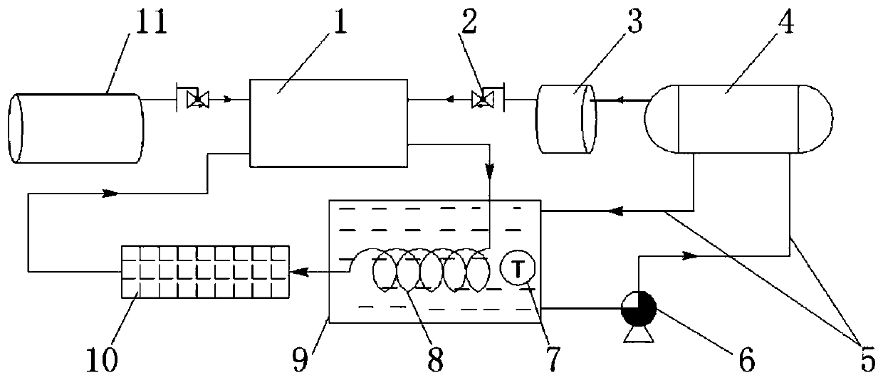
[0019] A schematic flow chart of Example 1 of a fuel cell power generation system using liquid oxygen as an oxidant is shown in figure 1 Shown: This process is applicable to the proton exchange membrane fuel cell system of static drainage technology. This embodiment mainly considers the characteristics of the fuel cell static drainage technology, separates the thermal management of the fuel cell itself from the thermal management of the liquid oxygen system, and uses the heat exchanger to realize the excess of thermal energy.
[0020] combine figure 1 , the present invention is composed of a fuel cell module 1, a control valve 2, a buffer tank 3, a liquid oxygen storage tank 4, a circulating water pipeline 5, a circulating water pump 6, a monitoring unit 7, a heat exchanger 8, a water tank 9, a radiator 10, The hydrogen supply system 11 is composed.
[0021] The fuel cell module 1, the heat exchanger 8 and the radiator 10 constitute a thermal management circuit of the fuel c...
Embodiment 2
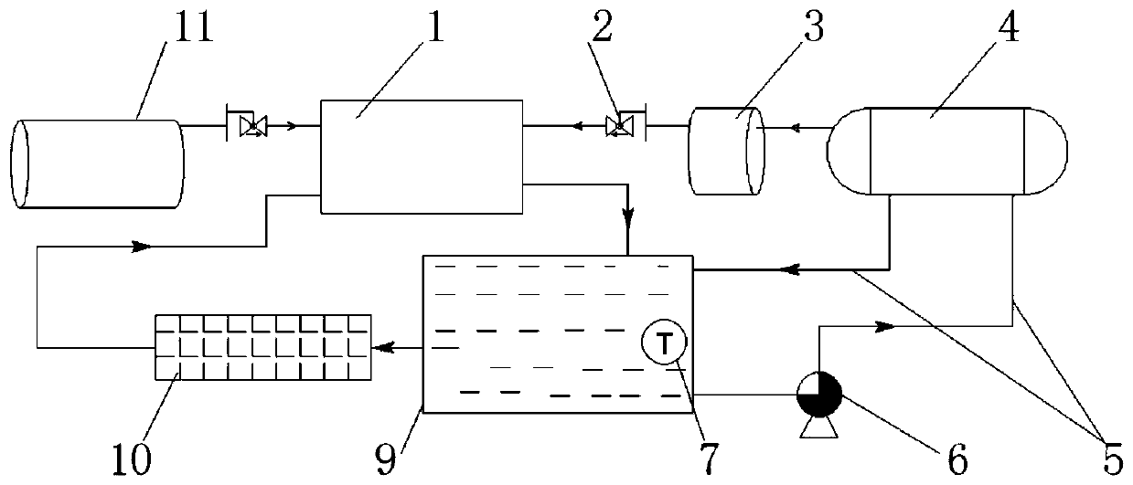
[0026] A schematic flow chart of Embodiment 2 of a fuel cell power generation system using liquid oxygen as an oxidant is shown in figure 2 Shown: This process is applicable to the proton exchange membrane fuel cell system with dynamic drainage technology. Considering the characteristics of the fuel cell dynamic water drainage technology, combining the thermal management waterway of the fuel cell itself with the thermal management waterway of the liquid oxygen system, the system will omit the heat exchanger 8 in Embodiment 1, and all the water circulation pipelines are at normal pressure Pipeline, the system is simpler. The specific implementation steps are as follows:
[0027] combine figure 2 , the present invention is composed of a fuel cell module 1, a control valve 2, a buffer tank 3, a liquid oxygen storage tank 4, a circulating water pipeline 5, a circulating water pump 6, a monitoring unit 7, a water tank 9, a radiator 10, and a hydrogen supply system 11. .
[00...
PUM
Abstract
The invention relates to a fuel cell power generation system using liquid oxygen as an oxidant, especially a proton exchange membrane fuel cell power generation system, comprising a proton exchange membrane fuel cell module, a liquid oxygen storage tank, a buffer tank, a water tank, a heat exchanger, and a control valve , radiator, circulating water pump, circulating water pipeline, monitoring unit and control module. The fuel cell's own heat is used to provide a heat source for the liquid oxygen storage tank to realize the vaporization of liquid oxygen, and then provide gaseous oxygen for the fuel cell as an oxidant. Compared with the traditional high-pressure cylinder oxygen storage method, the present invention has the advantages of large oxygen storage capacity, light weight, small volume, low working pressure, safety and reliability, fast oxidant filling speed, simple oxidant filling method, etc., and is especially suitable for A fuel cell power generation system with long-duration requirements in a closed system.
Description
technical field [0001] The invention relates to a fuel cell power generation system using liquid oxygen as an oxidant, in particular to a proton exchange membrane fuel cell power generation system using liquid oxygen as an oxidant in a closed system. Background technique [0002] A fuel cell is different from a battery in the traditional sense. It is a high-efficiency power generation device that converts chemical energy stored in fuel and oxidant into electrical energy electrochemically. It is also different from the traditional internal combustion engine. Although it needs fuel and oxidant like the internal combustion engine, it does not need to be burned, and can complete the chemical reaction at low temperature to realize the power generation function. There are many types of fuel cells, which can be divided into alkaline fuel cells, proton exchange membrane fuel cells, phosphoric acid fuel cells, molten carbonate fuel cells, and solid oxide fuel cells according to diffe...
Claims
Application Information
Patent Timeline
Application Date:The date an application was filed.
Publication Date:The date a patent or application was officially published.
First Publication Date:The earliest publication date of a patent with the same application number.
Issue Date:Publication date of the patent grant document.
PCT Entry Date:The Entry date of PCT National Phase.
Estimated Expiry Date:The statutory expiry date of a patent right according to the Patent Law, and it is the longest term of protection that the patent right can achieve without the termination of the patent right due to other reasons(Term extension factor has been taken into account ).
Invalid Date:Actual expiry date is based on effective date or publication date of legal transaction data of invalid patent.

