Shaft side drilling clamp

A drilling fixture and drilling mechanism technology, applied in clamping, manufacturing tools, supports, etc., can solve problems such as difficult chip removal

Inactive Publication Date: 2018-06-08
CHONGQING HOUQUAN TECH DEV CO LTD
View PDF6 Cites 3 Cited by
  • Summary
  • Abstract
  • Description
  • Claims
  • Application Information

AI Technical Summary

Problems solved by technology

[0004] The present invention intends to provide a shaft-side drilling jig to solve the problem that it is not easy to remove chips during the drilling process

Method used


Image

  • Shaft side drilling clamp
  • Shaft side drilling clamp

Examples


Embodiment Construction

[0015] The present invention will be further described in detail below through specific implementations:

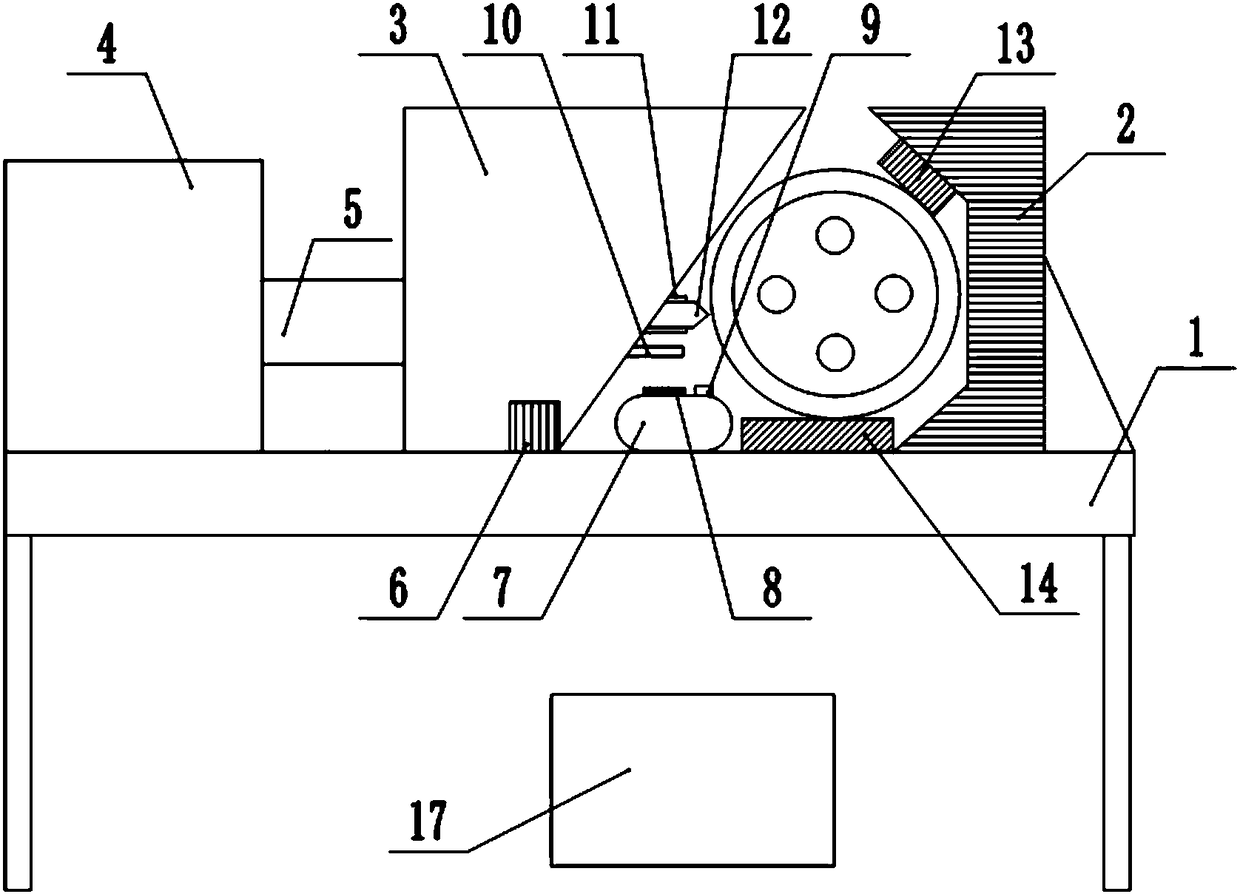
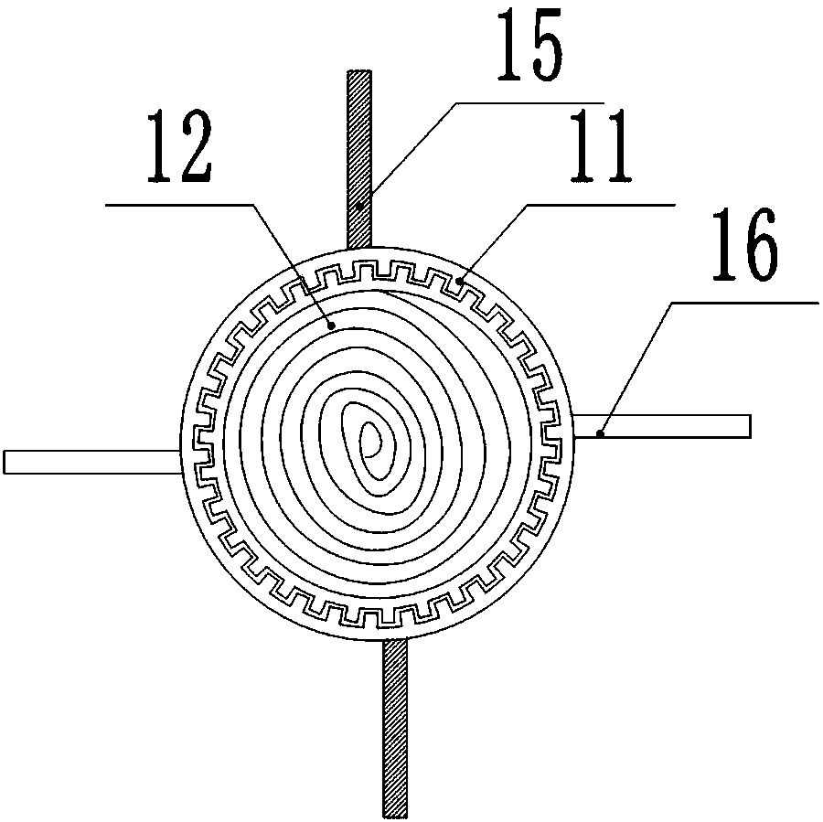
[0016] The reference signs in the drawings of the specification include: base 1, V-shaped block 2, compression slider 3, cylinder 4, piston rod 5, check valve 6, water bladder 7, second magnet 8, nozzle 9, chip stopper The block 10, the hoop 11, the drill bit 12, the wear-resistant pad 13, the support plate 14, the iron chip blade 15, the chip discharge blade 16, and the collection groove 17.

[0017] Such as figure 1 , figure 2 As shown, a shaft side drilling fixture includes a base 1, a V-shaped block 2 is fixed on the base 1, a wear-resistant pad 13 is fixed on the V-shaped block 2, and the opening direction of the V-shaped block 2 is provided with a pressing slide Block 3, the position on the pressing slider 3 that is directly opposite to the opening direction of the V-shaped block 2 is provided with an inclined surface, the lower part of the inclined surface is provided...


PUM


Abstract

The invention relates to a shaft side drilling clamp which comprises a base. A V-shaped block is fixed to the base. A pressing slider is arranged in the opening direction of the V-shaped block. The side, right opposite to the opening direction of the V-shaped block, of the pressing slider is provided with an inclined face. A check valve is arranged at the lower portion of the inclined face. The side, away from the V-shaped block, of the pressing slider is connected with a cylinder. A supporting plate is arranged between the V-shaped block and the pressing slider. A drill stem is rotationally connected into the pressing slider and connected with a motor. Teeth are formed in the outer wall of the drill stem. The drill stem is meshed with a hoop through the teeth. A plurality of scrap iron blades and a plurality of scrap discharge blades are hinged to the outer wall of the hoop. A first magnet is arranged on each scrap iron blade. A scrap stop piece is arranged on the inclined face of thepressing slider and located at the lower portion of the drill stem. A water bag is arranged on the base. A nozzle is arranged at the upper portion of the water bag. A second magnet is arranged on theupper portion of the water bag and is an electromagnet. The magnetic force of the second magnet is larger than the magnetic force of the first magnet. The problem that scrap discharging is not easy in the drilling process is solved by means of the shaft side drilling clamp.

Description

Technical field [0001] The invention relates to the field of clamping devices, in particular to a shaft side drilling fixture. Background technique [0002] With the improvement of people's living standards, people consume more and more automobiles, and automobile inspection and maintenance have become common. In the process of inspection or maintenance of automobiles and motorcycles, drilling operations are usually carried out. Drilling refers to the operation of drilling holes in accessories with a drill. The drilling methods are divided into handheld drilling and fixture drilling. Hand-held drilling is affected by mechanical force during the drilling process, and the hand will shake. Affecting the accuracy of drilling has been gradually eliminated. Fixture type drilling is used to clamp the workpiece during the drilling process, which avoids the problem of affecting the drilling accuracy due to shaking during the drilling process. [0003] However, in the two drilling methods,...

Claims


Application Information

Patent Timeline
Patent Type & Authority Applications(China)
IPC IPC(8): B23Q3/06B23Q11/00B23Q11/10
CPCB23Q3/06B23Q11/0042B23Q11/0064B23Q11/10
Inventor 卢加权
Owner CHONGQING HOUQUAN TECH DEV CO LTD
Why Eureka
Try Eureka