Lifting equipment for water conservancy project dam construction
A lifting equipment and water conservancy engineering technology, applied in the direction of lifting frame, lifting device, etc., can solve the problems of inconvenient transportation and unsafe transportation
- Summary
- Abstract
- Description
- Claims
- Application Information
AI Technical Summary
Problems solved by technology
Method used
Image

Examples
Embodiment 1
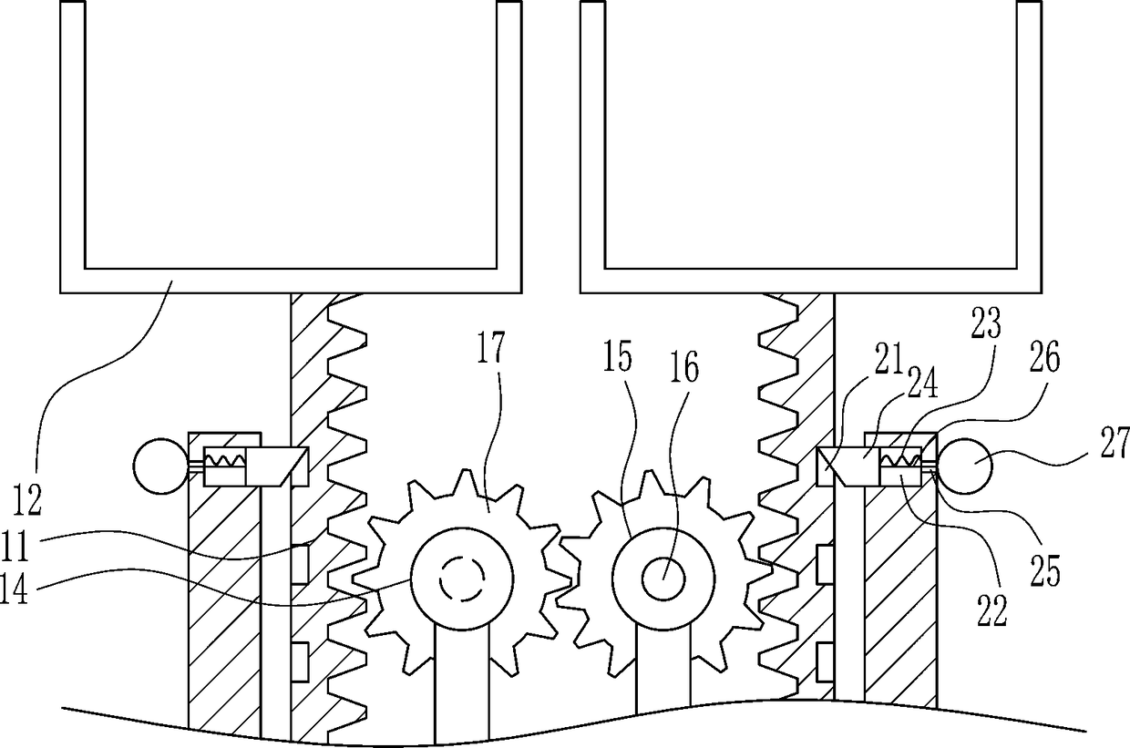
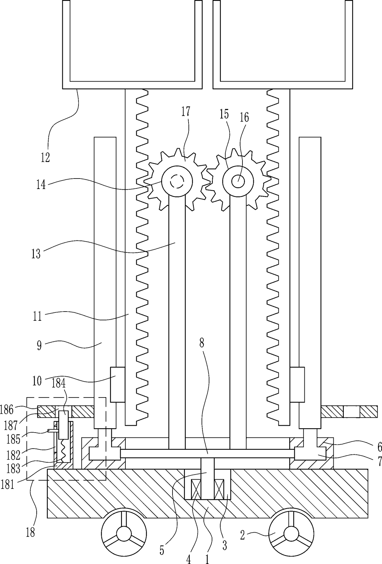
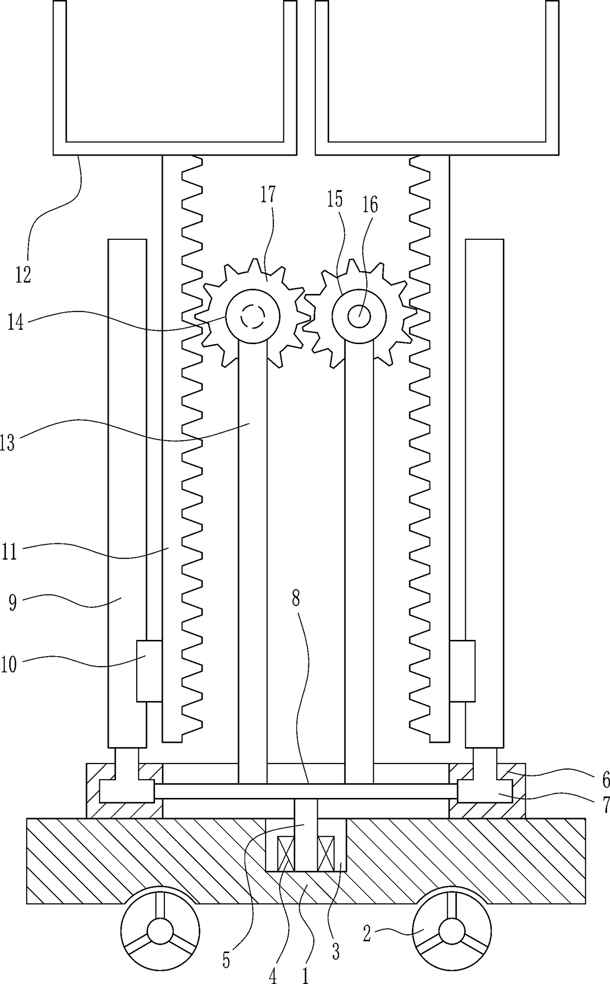
[0028] A lifting equipment for dam construction of water conservancy projects, such as Figure 1-5 As shown, it includes a bottom plate 1, a wheel 2, a first bearing seat 4, a first rotating shaft 5, an annular sliding rail 6, a first sliding block 7, a connecting rod 8, a first sliding rail 9, a second sliding block 10, and teeth Bar 11, discharge frame 12, mounting plate 13, motor 14, second bearing seat 15, second shaft 16 and gear 17, wheel 2 is installed on the lower side of bottom plate 1, and first groove 3 is opened in the upper middle of bottom plate 1, A first bearing seat 4 is arranged in the middle of the inner and lower wall of the first groove 3, a first rotating shaft 5 is arranged in the first bearing seat 4, an annular slide 6 is arranged on the upper side of the bottom plate 1, and the annular slide 6 slides symmetrically. The first slider 7 is connected, and the connecting rod 8 is connected between the inner sides of the first slider 7 on the left and right ...
Embodiment 2
[0030] A lifting equipment for dam construction of water conservancy projects, such as Figure 1-5 As shown, it includes a bottom plate 1, a wheel 2, a first bearing seat 4, a first rotating shaft 5, an annular sliding rail 6, a first sliding block 7, a connecting rod 8, a first sliding rail 9, a second sliding block 10, and teeth Bar 11, discharge frame 12, mounting plate 13, motor 14, second bearing seat 15, second shaft 16 and gear 17, wheel 2 is installed on the lower side of bottom plate 1, and first groove 3 is opened in the upper middle of bottom plate 1, A first bearing seat 4 is arranged in the middle of the inner and lower wall of the first groove 3, a first rotating shaft 5 is arranged in the first bearing seat 4, an annular slide 6 is arranged on the upper side of the bottom plate 1, and the annular slide 6 slides symmetrically. The first slider 7 is connected, and the connecting rod 8 is connected between the inner sides of the first slider 7 on the left and right ...
Embodiment 3
[0033] A lifting equipment for dam construction of water conservancy projects, such as Figure 1-5 As shown, it includes a bottom plate 1, a wheel 2, a first bearing seat 4, a first rotating shaft 5, an annular sliding rail 6, a first sliding block 7, a connecting rod 8, a first sliding rail 9, a second sliding block 10, and teeth Bar 11, discharge frame 12, mounting plate 13, motor 14, second bearing seat 15, second shaft 16 and gear 17, wheel 2 is installed on the lower side of bottom plate 1, and first groove 3 is opened in the upper middle of bottom plate 1, A first bearing seat 4 is arranged in the middle of the inner and lower wall of the first groove 3, a first rotating shaft 5 is arranged in the first bearing seat 4, an annular slide 6 is arranged on the upper side of the bottom plate 1, and the annular slide 6 slides symmetrically. The first slider 7 is connected, and the connecting rod 8 is connected between the inner sides of the first slider 7 on the left and right ...
PUM
 Abstract
Description
Claims
Application Information
 - R&D Engineer
- R&D Manager
- IP Professional
- Industry Leading Data Capabilities
- Powerful AI technology
- Patent DNA Extraction
Browse by: Latest US Patents, China's latest patents, Technical Efficacy Thesaurus, Application Domain, Technology Topic.
© 2024 PatSnap. All rights reserved.Legal|Privacy policy|Modern Slavery Act Transparency Statement|Sitemap