
An extension structure suitable for adjusting the position of the center of gravity of tenon-connected rotor blades

A rotor blade and center-of-gravity position technology, applied in the direction of blade support elements, machines/engines, mechanical equipment, etc., can solve problems such as uneven contact stress and bearing capacity

Active Publication Date: 2020-05-01
INST OF ENGINEERING THERMOPHYSICS - CHINESE ACAD OF SCI +1
View PDF3 Cites 0 Cited by
  • Summary
  • Abstract
  • Description
  • Claims
  • Application Information

AI Technical Summary

Problems solved by technology

[0003] Aiming at the technical problem of the uneven contact stress bearing capacity of the root extension section and the working surface on both sides of the tenon / tenon teeth in the existing rotor blade structure, the present invention provides an extension suitable for the adjustment of the center of gravity of the tenon-connected rotor blade. The root structure can realize the load sharing design requirements of the root section of the blade body under the action of centrifugal force and aerodynamic bending moment and the tenon / tenon tooth working surface in the working state, and can be applied in the fields of gas turbines, aeroengines, etc.

Method used


Image

  • An extension structure suitable for adjusting the position of the center of gravity of tenon-connected rotor blades
  • An extension structure suitable for adjusting the position of the center of gravity of tenon-connected rotor blades

Examples


Embodiment Construction

[0021] The present invention will be further described in detail below in conjunction with the examples, the following examples are explanations of the present invention, and the present invention is not limited to the following examples.

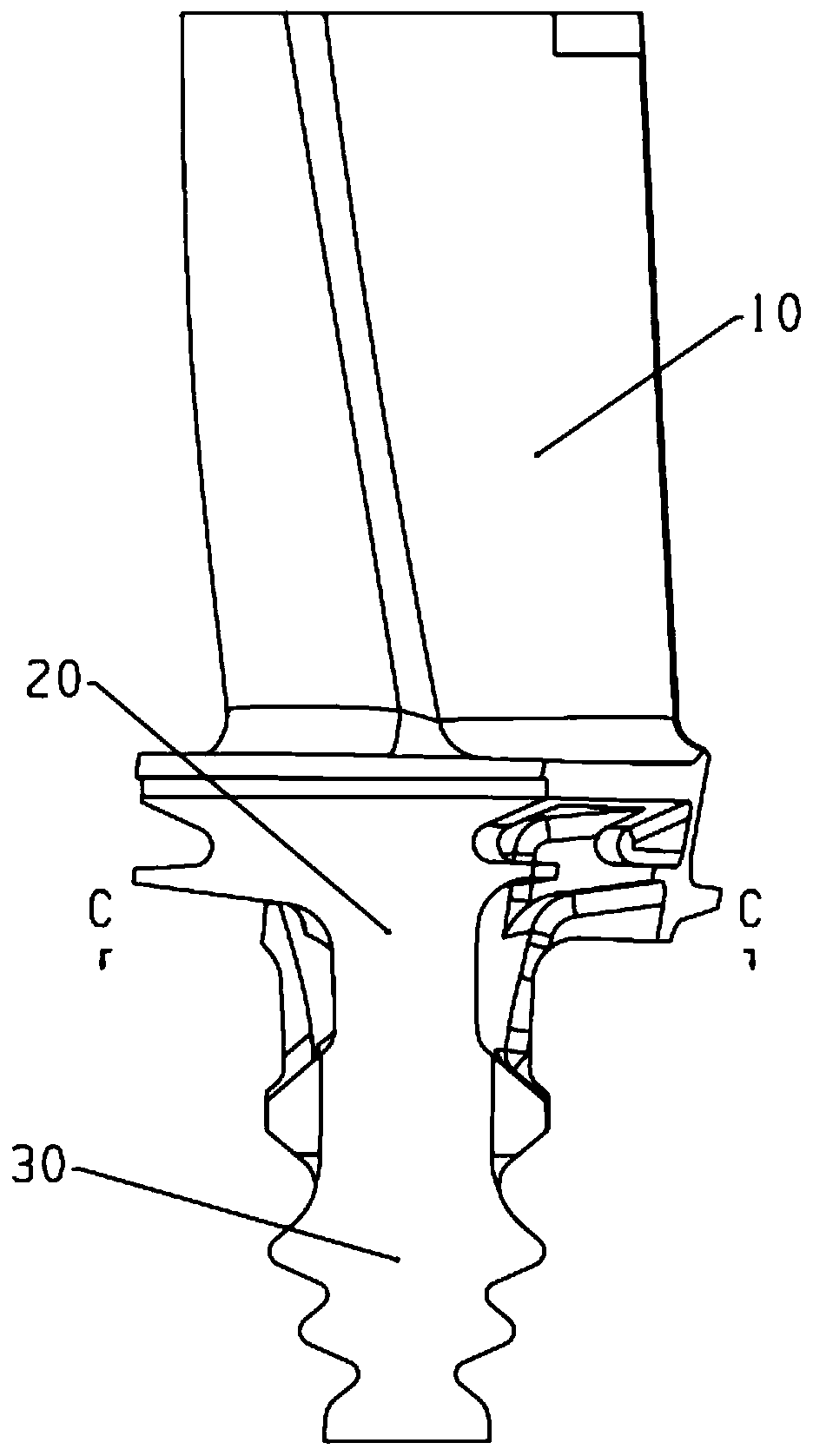
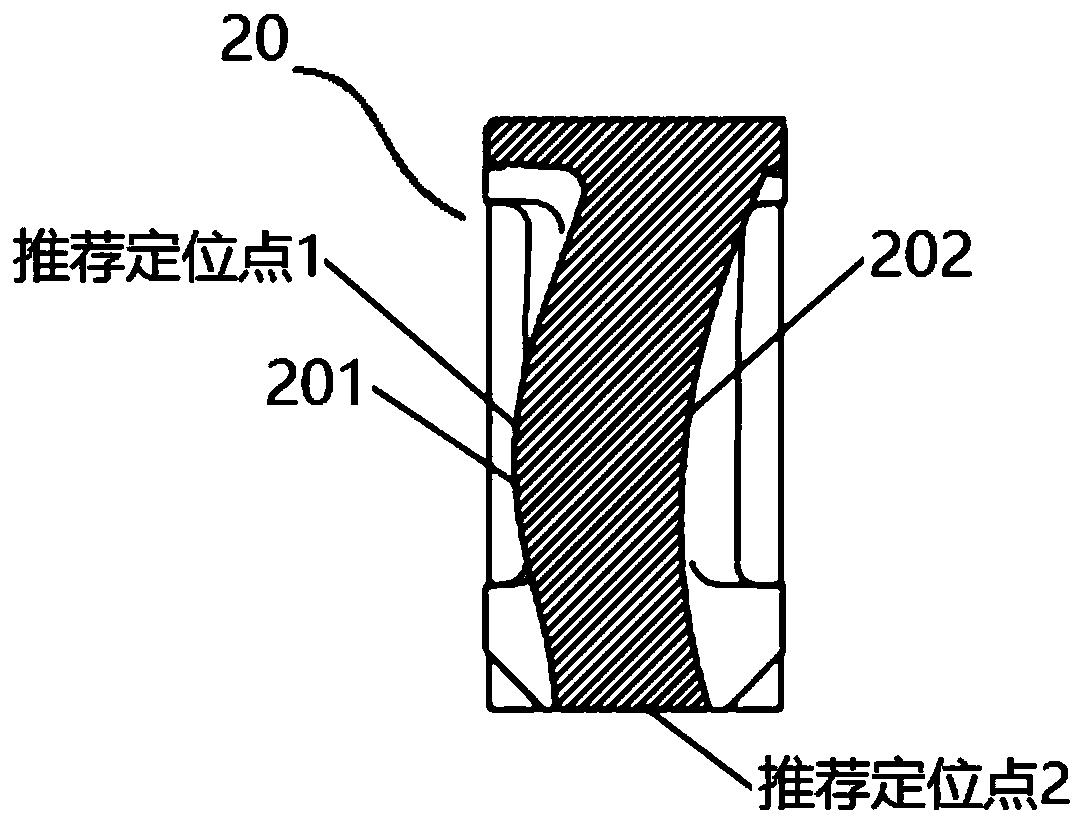
[0022] figure 1 It is a schematic diagram of the structure of the tenon-jointed rotor blades in a certain type of turbofan engine adopting the root extension structure of the present invention. Such as figure 1 As shown, the rotor blade is sequentially divided into three parts: the blade body section 10 , the root extension section 20 and the tenon section 30 from top to bottom. Among them, such as figure 2 As shown, the leaf back side 201 and the leaf basin side 202 of the root extension section 20 adopt an asymmetrical profile line (see the C-C sectional view), and use the asymmetrical line change law to realize the adjustment of the center of gravity of the blade. The two sides of the root section 20 can also be shaped by the wing / bl...


PUM


Abstract

The invention relates to a root extension structure suitable for adjusting the gravity center position of a tenon connection rotor blade. The profile lines on the two sides of a root extension sectionare basically the same as the profile lines on the two sides of the root region of a blade body section, or the profile lines on the two sides of the root section of the blade body section are basically the same as the profile lines on the two sides of the root region of the blade body section, or, and the profile lines at the back side of a blade and the side of a blade basin are at least in anasymmetric wing linear type line, and the center of gravity of the cross section of the root extension section is adjusted to be deviated from one side of the back side of the blade. The root extension structure can be applied to gas compressor / turbine rotor blade structures of an aero-engine and a gas turbine, the wing / blade type lines of the root extension section are optimized, so that the asymmetric adjustment of contact stress of contact surfaces on the two sides of tenon teeth is realized. Under the working state of the blade, the blade body of the blade can be stressed by a pneumatic bending moment, and the asymmetric tenon teeth contact stress can achieve the purpose of adjusting the symmetry. Therefore, the uniform load design targets of the contact stress between the tenons andthe tenon teeth on the two sides of the blade are achieved. The root extension structure has the huge prospect of engineering application.

Description

technical field [0001] The invention belongs to the field of gas turbine or aero-engine rotor blades, and in particular relates to a tenon-connected rotor blade root extension structure for adjusting the center of gravity position, which can be applied to compressor rotor blades or turbine rotor blades adopting a tenon / tenon-tooth connection type. Background technique [0002] The structural design of tenon-joint compressor rotor blades and turbine rotor blades is a problem of great practical engineering significance in the fields of gas turbines and aeroengines. In the structural design of existing gas turbines and aero-engines, the root section of the rotor blade is usually designed as a simple straight-face structure with equal thickness or the transition from the root of the blade body to the tenon is realized by stretching and forming. However, considering that in the actual working state, the rotor blades of the existing structure, especially the turbine rotor blades w...

Claims


Application Information

Patent Timeline
Patent Type & Authority Patents(China)
IPC IPC(8): F01D5/30
CPCF01D5/3007
Inventor 杜强柳光刘军王沛高金海杨晓洁刘红蕊徐庆宗胡嘉麟
Owner INST OF ENGINEERING THERMOPHYSICS - CHINESE ACAD OF SCI
Learn More