Test clamp

A technology of test fixtures and test needles, which is applied in the direction of the measuring device casing, etc., can solve the problem of high equipment cost, and achieve the effects of low manufacturing cost, high test efficiency, and simple structure

Pending Publication Date: 2018-06-08
昆山威典电子有限公司
View PDF0 Cites 5 Cited by
  • Summary
  • Abstract
  • Description
  • Claims
  • Application Information

AI Technical Summary

Problems solved by technology

[0004] The defect of the prior art is that the driving mechanism is required to drive the test needle holder to move upwards, and the equipment cost is high

Method used


Image

  • Test clamp
  • Test clamp
  • Test clamp

Examples


Embodiment Construction

[0042] The technical solutions of the present invention will be further described below in conjunction with the accompanying drawings and through specific implementation methods.

[0043] This preferred embodiment provides a test fixture, which is mainly but not limited to the performance test of terminal blocks, so that the test fixture can separate the test fixture from the product to be tested after the test is completed without a driving mechanism, reducing the cost of the test fixture. manufacturing cost.

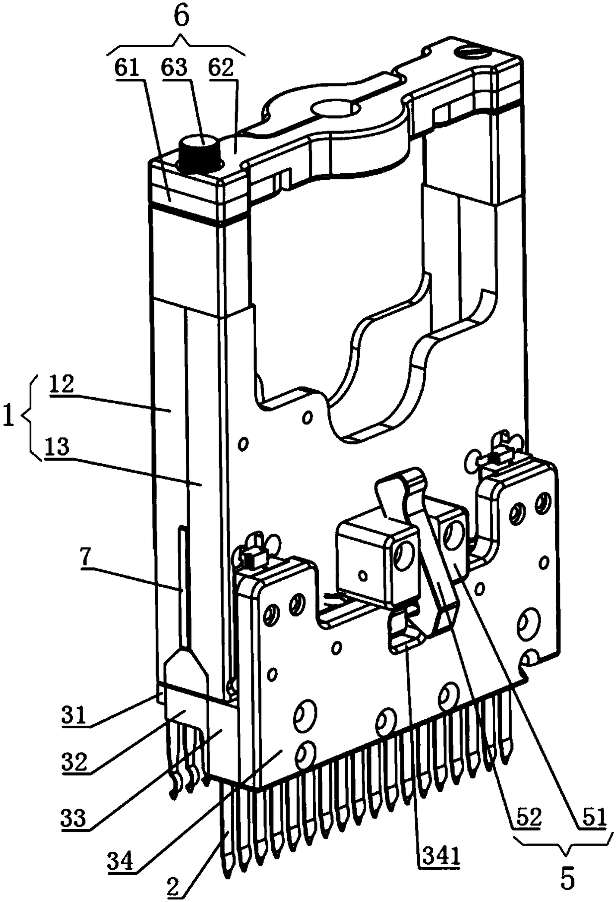
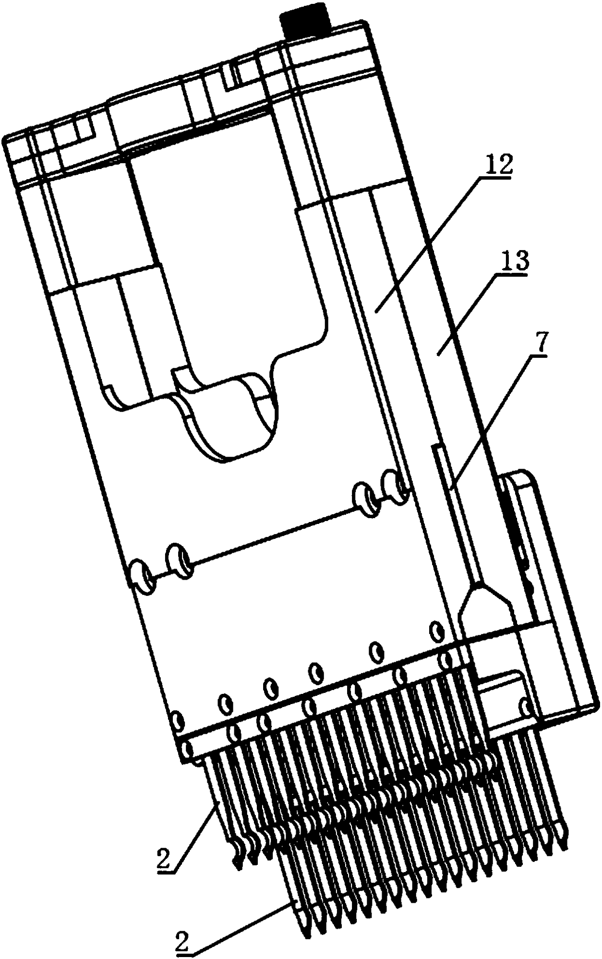
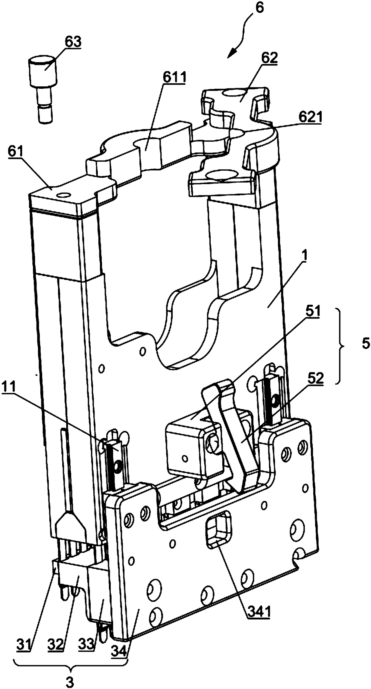
[0044] Such as figure 1 and figure 2 As shown, the test fixture provided in this embodiment includes a mounting frame 1, a plurality of test needles 2, a support seat 3 and an elastic member. One end of the support base 3 is used to abut against the product 8 to be tested; the installation frame 1 can slide along the support base 3 in a direction approaching or away from the product 8 to be tested under the action of an external force, and the installation frame 1 i...


PUM


Abstract

The present invention relates to the technical field of wiring terminal tests, and especially discloses a test clamp. The test clamp comprises a support seat, an installation rack, a plurality of testneedles and an elastic component. One end of the support seat is configured to abut against a product to be tested; the installation rack can slide close to or far away from the product to be testedalong the support seat, and is located at one end, far away from the product to be tested, of the support seat; one ends of the test needles are connected with one end, close to the product to be tested, of the installation rack, and the other ends of the test needles are configured to be inserted into the product to be tested; and one end of the elastic component is connected with the support seat, the other end of the elastic component is connected with the installation rack, and the elastic component can drive the installation rack to be far away from the product to be tested so as to allowthe test needles to be far away from the product to be tested. After the test of the product to be tested is finished, an external force is only removed, the elastic component drives the installationrack to move upwards, the test needles are pulled out from the product to be tested at the same time, the product to be tested cannot be damaged or damaging of the test needles themselves cannot happen, and therefore, the test clamp is simple in structure, low in manufacturing cost and high in test efficiency.

Description

technical field [0001] The invention relates to the technical field of terminal testing, in particular to a testing fixture. Background technique [0002] With the increasing degree of industrial automation and stricter and more precise industrial control requirements, the usage of terminal blocks is gradually increasing, and the requirements for the accuracy and efficiency of quality inspection of terminal blocks before leaving the factory are also getting higher and higher. [0003] A test fixture for a terminal block in the prior art includes a test needle holder equipped with test needles, a bearing platform for carrying the product to be tested, and a driving mechanism for driving the test needle holder to move up and down. After the test is completed, the driving mechanism drives the test needle frame to move upward, so that the test needle is separated from the test terminal of the product to be tested on the carrying platform. [0004] The defect of the prior art is...

Claims


Application Information

Patent Timeline
IPC IPC(8): G01R1/04
CPCG01R1/04
Inventor 郑建生
Owner 昆山威典电子有限公司
Why Eureka
Try Eureka